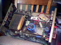
Well, I finished my Ball Mill to pulverize my break chips, and its..its..*sniff*..beautiful man *sniff*....
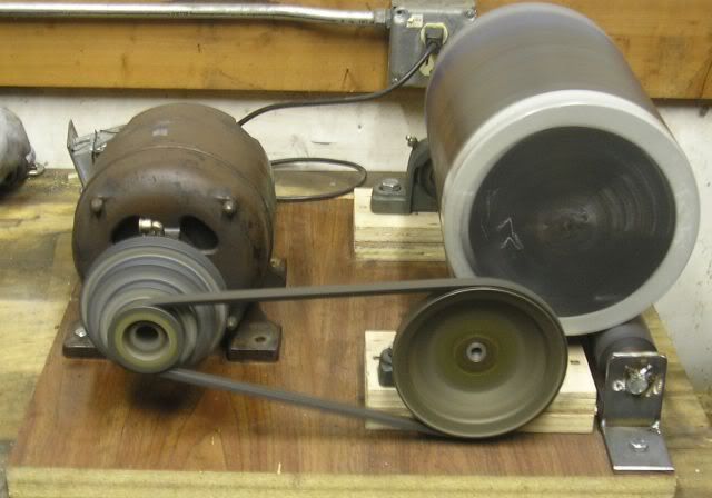
...OK, it won't win any prizes in the looks dept.,but it works exceedingly well. In the picture it’s humming along at around 60 rpm beating the chips into submission. I used 8 cast iron “T” fittings at about 2 lbs. apiece for the “balls”.
This is a picture of the break chips, clinging to a small pocket magnet used to retrieve screws, before processing ..

The first thing I did was to heat the chips to around 1400 deg F (red heat) burning off any oils/breakfluid contaminants, and then cooling them rapidly by pouring through the air into a cast iron pan. The rapid cooling causes the chips to become brittle from the stress. I then ran them in the mill for around 6 hours, this was the result…
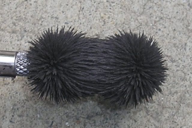
Two thing jump out, how densely packed the powder is around the flux lines, and how black it is. Grey iron is peppered with little pockets of graphite, this is the form the carbon takes in the metal. It is along these pockets that the metal breaks when struck. As the iron is reduced by the mill, the graphite is freed from its metal prison.
The next step is to separate the graphite from the iron powder. This is done by float separating. I put about a cup or so of iron in a glass jar then poured lacquer thinner to about the 2 cup level. I then stirred it hard enough to suspend the iron. After it settles, a layer of graphite forms on top of the iron. I then stir it just hard enough to suspend the graphite. While the graphite is still swirling, I pour it off into a filtered funnel, cleaning the thinner for the next batch. The iron is then spread out in a pan OUTSIDE to dry. After doing 2-3 cups of powder, (it was still black, telling me I need to repeat this a few times) I got the graphite you see here…
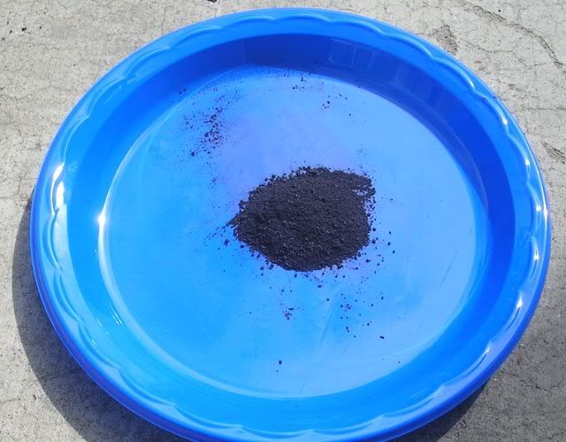
It is graphite, rubbing between your finger and thumb, it feels like oil. First unexpected benny, a supply of graphite lubricant") . The mass of the powder before and after cleaning went up 7% . That’s more than I expected. I am re-running the powder through the mill for 30-40 hours to reduce/clean it as much as I can. Right now its loose-filled mass is around 67% of solid iron.
. The mass of the powder before and after cleaning went up 7% . That’s more than I expected. I am re-running the powder through the mill for 30-40 hours to reduce/clean it as much as I can. Right now its loose-filled mass is around 67% of solid iron.
After I clean the powder that’s in the mill now, I am going to ballpark its relative permeability by burying a coil in the powder.
Stay tuned…
Casey Brown
...OK, it won't win any prizes in the looks dept.,but it works exceedingly well. In the picture it’s humming along at around 60 rpm beating the chips into submission. I used 8 cast iron “T” fittings at about 2 lbs. apiece for the “balls”.
This is a picture of the break chips, clinging to a small pocket magnet used to retrieve screws, before processing ..
The first thing I did was to heat the chips to around 1400 deg F (red heat) burning off any oils/breakfluid contaminants, and then cooling them rapidly by pouring through the air into a cast iron pan. The rapid cooling causes the chips to become brittle from the stress. I then ran them in the mill for around 6 hours, this was the result…
Two thing jump out, how densely packed the powder is around the flux lines, and how black it is. Grey iron is peppered with little pockets of graphite, this is the form the carbon takes in the metal. It is along these pockets that the metal breaks when struck. As the iron is reduced by the mill, the graphite is freed from its metal prison.
The next step is to separate the graphite from the iron powder. This is done by float separating. I put about a cup or so of iron in a glass jar then poured lacquer thinner to about the 2 cup level. I then stirred it hard enough to suspend the iron. After it settles, a layer of graphite forms on top of the iron. I then stir it just hard enough to suspend the graphite. While the graphite is still swirling, I pour it off into a filtered funnel, cleaning the thinner for the next batch. The iron is then spread out in a pan OUTSIDE to dry. After doing 2-3 cups of powder, (it was still black, telling me I need to repeat this a few times) I got the graphite you see here…
It is graphite, rubbing between your finger and thumb, it feels like oil. First unexpected benny, a supply of graphite lubricant
. The mass of the powder before and after cleaning went up 7% . That’s more than I expected. I am re-running the powder through the mill for 30-40 hours to reduce/clean it as much as I can. Right now its loose-filled mass is around 67% of solid iron.After I clean the powder that’s in the mill now, I am going to ballpark its relative permeability by burying a coil in the powder.
Stay tuned…
Casey Brown
Pics look good. Can't you get your hands on any of the right type of iron without having to break down the reinvented wheel yourself?
Nope...see this thread for details...
http://www.diyaudio.com/forums/showthread.php?s=&threadid=55929
Casey
Hey, impressive start! I think a bunch of us are still waiting sceptically to see the Mu results though. I'll bet some 6AL5s on the Mu comes out under 20. Any other bets?
I tried some crushed ferrite core powder once. Original Mu was 5000. The powder, even packed, came out around 15. But the iron "stuff" has the advantage that its malleable, so maybe can do better.
Don
I tried some crushed ferrite core powder once. Original Mu was 5000. The powder, even packed, came out around 15. But the iron "stuff" has the advantage that its malleable, so maybe can do better.
Don
Hey, impressive start!
Thank you

I think a bunch of us are still waiting sceptically to see the Mu results though.
Sceptisism is a good thing.
I'll bet some 6AL5s on the Mu comes out under 20. Any other bets?
Do you want my snail mail address now or later ?
I don't have any 6AL5s, but I got a pair of 26s I'll put up.I tried some crushed ferrite core powder once. Original Mu was 5000. The powder, even packed, came out around 15. But the iron "stuff" has the advantage that its malleable, so maybe can do better.
Ah..but at what frequency was the Mu speced at? I have seen the specs for dozens of ferrite cores, the lowest cut off I've seen on any of them was 500 hz, and if memory serves, I haven't seen that high of Mu on any core with a cut off lower than 100khz.
Powdered iron ,without silicon, has a Mu of 5000 down to dc. The fact that its malleable is also an advantage, I think the contact point grain to grain will be larger, resulting in a more linear B-H curve.
My minimum target is a Mu of 200

Casey
scrap metal
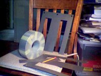
my latest trip to the scrap metal yard, $1.00 a pound
The toroids are 1KW M6 , got a half dozen, and the extra long E -I cores must be a couple of KW, M6 with MgO2 coating, bought a big box of them. I figure, the bigger the core the fewer the turns to wind for an OT and the better the bass, also the toroids are big enough that I can get the wire spool thru the hole.
Attachments
Don,
 Holy magnetic induction Batman!!
A PP 833 in your future perhaps ?
I want YOUR salvage yard..mine is good for parts off of apple sorters ect.
Nice score.
Casey
The toroids are 1KW M6 , got a half dozen, and the extra long E -I cores must be a couple of KW, M6 with MgO2 coating, bought a big box of them.
Holy magnetic induction Batman!!A PP 833 in your future perhaps ?
I want YOUR salvage yard..mine is good for parts off of apple sorters ect.
Nice score.
Casey
Those were the ones that were small enough to carry out. Should seen the other ones that got away!
Try around Portland, with Tektronix there, must be something. I've heard the garbage they through out around Santa Clara, Ca is gold plated. Of course, there's always Ebay, but the shipping on iron will kill ya.
Try around Portland, with Tektronix there, must be something. I've heard the garbage they through out around Santa Clara, Ca is gold plated. Of course, there's always Ebay, but the shipping on iron will kill ya.
Here's a nice long E transformer, part of a Kepco ATE --- , 500 Watt linear power supply I got on Ebay. Cost me $9.99 and $50+ for shipping. Was supposed to be a working power supply, but arrived with the heatsink/power transistors missing. The usual Ebay -------! It came from Washington state too! The core is really thick, so can probably get two cores out of it. But it happens to have a nice HV winding on it already, so may keep as a power xfmr. or I may just fix the supply. Its also an enameled core, so a bit of a headache to get apart. Haven't checked to see if its M6 yet. But I would guess that the other Kepco ATE --- 500 Watt models have the same xfmr size in them. Can find them cheap occasionally. Low voltage models are usually cheap.
Its not easy to find long E laminations, even new. So this is a nice find. The long E lams have low leakage inductance compared to the usual scrapless ones. Was the secret behind the best AcroSound output xfmrs.
Its not easy to find long E laminations, even new. So this is a nice find. The long E lams have low leakage inductance compared to the usual scrapless ones. Was the secret behind the best AcroSound output xfmrs.
Attachments
I checked the Kepco ATE 500 Watt power supply xfmr lams, and they are indeed M6, so this is premium long E stuff for winding OTs. (checked using a variac and a current probe to scope)
For those who might wish to consider this route (instead of using powdered iron!) to getting a premo core (enough for making 2 xfmrs with square winding cores), here are the core dimensions:
Overall: 6 inch x 4.5 in. x 2.8 in. thick stack
tongue: 1.5 in. x 2.8 in. thick stack
winding windows: 4.5 in. x .75 in.
Also, I checked on a Kepco ATE 250 Watt power supply and it has the exact same xfmr. but with 1/2 the stack thickness, 1.4 inch. This is just right for making 1 OT with a square winding core.
Using the 1.4 inch stack, 250 W core, this will give about 250/3 = 80 Watts at 20 Hz bottom (flux up to saturation), 250/2 = 125 W for guitar amp rating at 30 Hz (Hammond rating too), and for a true high fi rating at 7500 gauss at 20 Hz, this would give 40 Watts audio power. These are all Push Pull amplifier ratings.
For SE you will have to put a spacer in the lamination E to I gap. This will typically reduce audio power ratings by about 1/4 from P-P rating.
Don
Don, come now.
Who wouldn't want to make a powdered core ? Just think of all the good times you would be depriving yourself...seeing the "deer in the headlights" expression on the face of the break guy as youtry to explain why you want his chips, screening all the garbage that was thrown in the chips, playing with extreme heat to clean/harden them , building then listening to your ball mill, getting the black off your hands after playing with the stuff...I could go on, but just talking about it is raising my level of excitement!!
If it works, it will have been more than worth it. If not, the knowledge I gained will have been just worth it. From my viewpoint its a win-win.
Casey
For those who might wish to consider this route (instead of using powdered iron!)
Who wouldn't want to make a powdered core ? Just think of all the good times you would be depriving yourself...seeing the "deer in the headlights" expression on the face of the break guy as youtry to explain why you want his chips, screening all the garbage that was thrown in the chips, playing with extreme heat to clean/harden them , building then listening to your ball mill, getting the black off your hands after playing with the stuff...I could go on, but just talking about it is raising my level of excitement!!
If it works, it will have been more than worth it. If not, the knowledge I gained will have been just worth it. From my viewpoint its a win-win.
Casey
Wow! I hadn't thought of all those fun benefits. Now you've got me excited. Could you send a truck load of the stuff over so I can fill up our sand box with it?
When I get tired of playing in it (and I can use a magnet to clean up), the cats can use it. Maybe can use a magnetic separator and sell it as cat litter. The possibilities are endless! Could put it on the snow in winter for traction, then pick it up again with a magnet in the Spring. How about as an additive to radiator fluid, just put a magnet near any leak and it will automatically plug it up.
Think of the military uses! and they pay big money. Put it on a road in a magnetized state. Well, just think of what ordinary dust does to tank treads. And I'll bet it will work for radar absorbing stealth coatings too, can even leave the carbon in. Ya know, I'll bet it would even increase octane in gasoline. Why run the exhaust thru a catalytic convertier when you can just mix the catalyst in the gasoline. And diesel. Whoa! The soot would probably coalesce right around the iron dust. Then just use a magnet to clean up the exhaust. Endless possibilities!!
Don
I checked the Kepco ATE 500 Watt power supply xfmr lams, and they are indeed M6, so this is premium long E stuff for winding OTs. (checked using a variac and a current probe to scope)
How did you determine this?
John
measuring laminations
I use a variac to vary the voltage on a winding on the xfmr. The current waveform is monitored by current probe on an oscilloscope. (DC to 50 Mhz response TEK A6302 probe) As the voltage is increased, M6 develops a square wave current initially which then develops a spike at the END of the square wave as one nears the rated voltage. The spike rapidly grows in magnitude near and above the rated voltage. The square wave is most likely due to the square hysteresis curve of square orthonol material.
With non-oriented iron, the current starts out as a triangular waveform and develops a spike in the center at the triangle peak. Similarly, the spike grows rapidly around the rated voltage and above.
Toroids with M6 have an especially clean square wave initially, and would be expected to do so since 100% of the material is currectly oriented to the field. This was all learned by testing known transformer materials, and has been very consistent. Probably, something like round permalloy would give a different waveform. I haven't tested anything like M4 or other rarer materials, so this test may not identify them uniquely from grain oriented M6. But for audio, any grain oriented material is likely to be suitable unless it is cross grain oriented at 90 degrees to the field. (Some HF materials are this way.)
Another test one could do would be to measure inductance at just below the point of the spike forming current level and calculate material Mu from physical dimensions and turns (a fair amount of work however). The M6 will have a significantly higher Mu than the non grain oriented material.
Don
A few more observations on xfmr current waveform measurements.
At very low voltage, WELL below rated voltage, the current waveform is usually a sine wave (of course this depends on how good the power line sine wave is in your area, it has deteriorated significantly to a flat top here over the years, computers,electronics....) for either oriented or non-oriented material.
The initial current spike for an M6 toroid is very narrow at the end of the square wave current. For M6, E lams its broader. The long E lams are in-between. The narrowness of this spike is a good measure of what percentage of the lam is correctly oriented with the field. (the back side of E lams between the fingers are incorrectly oriented)
The voltage at which the spike appears is a good indication of weather the xfmr winding has enough turns or iron for the rated voltage. Cheap (skimped on the iron), and also old transformers (110V, 115V) , tend to have the saturation spike set in early. They operate at higher flux level then and suffer higher losses (get hotter, hum and buzz more too).
Thick laminations in a xfmr are most likely to be non-oriented iron.
Don
- Status
- This old topic is closed. If you want to reopen this topic, contact a moderator using the "Report Post" button.
- Home
- Amplifiers
- Tubes / Valves
- DIY Powdered Core Progress Report