I would like to wind an O/P Tx for a SE, 6c33c-b, but havent much of a clue how to go about it.
Have any guys done this, what size of Tx did you use, and probably the most hard question is how many turns per winding/interleaves/air-gaps did you use?
I should be able to source transformer components, frames stampings, wire etc, in most common VA sizes and I recon I could set up the lathe to do the winding.
Any help much appreciated!--I would love to ditch the power Tx Im using at the moment and replace it with something more appropriate!
Thanks!
Re: Interesting program!
It's free, thanks to Yves
http://geek.scorpiorising.ca/yves.html
Alastair E said:Where would I find a download of this calculator?--How much does it cost?
It's free, thanks to Yves
http://geek.scorpiorising.ca/yves.html
New version available
Somewhat improved maths at Hi freq and lighter (MS jet engine no longer used)
http://perso.wanadoo.fr/yves.monmagnon/OPT_da-211.zip
Have fun !
Yves.
Somewhat improved maths at Hi freq and lighter (MS jet engine no longer used)
http://perso.wanadoo.fr/yves.monmagnon/OPT_da-211.zip
Have fun !
Yves.
Thanks!
Very good of you to go to the trouble of both supplying the link to your calculator download AND go to the trouble of setting up the projet for me.
Currently Im using a mains Tx, and using neg-feedback to compensate for its lack of bass response, but this is a pretty poor way of doing things!--Sounds good though, so long as you dont over drive it!
operating point
If I was to follow your excellent layout for the Tx, would the fact Im using 310v +B and cathode bias with around 190mA on the 6c33 affect the results?
(or can you suggest a more favourable conditions for this tube?)
In your example, the Rp is set to 150 ohm, O/P imp is (I think) 6.6 ohm
Ive been looking at 600 as primary imp, with Rp at 80 ohm--Or maybe Im just missing something important!
Thanks again!
Re Operating point
So, I was a bit pessimistic.
At 600 Ohms and with 190mA, the Tx could be slightly smaller.
However, it will work as is.
But, is the cost an issue ?
I fear that the suggested size of the laminations not be an "Imperial Standard" and perhaps not easily available.
If so, let me know as precise as possible mecanical data for the iron and for the bobin.
If you installed the program, we could share the "project" files.
Yves.
They say bigger is better!
Im not too worried by the cost of the lams/frame bobbin etc, as these would be a tiny fraction the cost of a premium Tx by a reputable maker!
Most things in this country are done in Metric these days, so I guess Tx and parts for them will be available easily, if not--very close!--The code for the iron--How does that relate to the physical dimensions?
My only doubt, would be the composition of the iron--Not sure what M6x is, or if its used widely here, but at least with standard iron the specs should be fair, and infinately better than my mains Tx!.
Ive downloaded the prog, and have played around a while with it, just to get the hang of how it works--It really does seem to think of everything--You must be a genius to be able to write it!
Ill try and do a project, and see how it works out using the prog. properly.
Re: They say bigger is better!
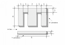
(See attached figure)
The code number is the lenght of the I part.
So, for the EI126, the I is 126mm long by 126/6=21mm wide, the tongue width is 126/3=42mm and so on.
The second number (if present) is the height of the stack. When absent, it is somewhat equal to the tongue width (square section).
i.e. "EI126-50" means a 42 wide by 50mm height stack.
Hope this helps.
Looking to steel grade, use the thinest you find, M6X is 0.35mm thick, while standard is 0.5mm or even more.
Of course this doesn't tell you about the included silicon, you must trust your supplier !
Nevertheless, in an SE design, the permeability is not the main criterion because the gap reduces it to a vy lo value anyway.
More important is the saturation.
M6X accept near 30% more induction than standard lams for the same amount of distortion at the lower end.
My faith is that M6X still works satifactory at up to 1.3Tesla while std should not be driven at more than 1T.
Yves.
Here are the constant ratios for the so called "scrapless" laminations.Alastair E said:Im not too worried by the cost of the lams/frame bobbin etc, as these would be a tiny fraction the cost of a premium Tx by a reputable maker!
Most things in this country are done in Metric these days, so I guess Tx and parts for them will be available easily, if not--very close!--The code for the iron--How does that relate to the physical dimensions?
(See attached figure)
The code number is the lenght of the I part.
So, for the EI126, the I is 126mm long by 126/6=21mm wide, the tongue width is 126/3=42mm and so on.
The second number (if present) is the height of the stack. When absent, it is somewhat equal to the tongue width (square section).
i.e. "EI126-50" means a 42 wide by 50mm height stack.
Hope this helps.
My only doubt, would be the composition of the iron--Not sure what M6x is, or if its used widely here, but at least with standard iron the specs should be fair, and infinately better than my mains Tx!.
Looking to steel grade, use the thinest you find, M6X is 0.35mm thick, while standard is 0.5mm or even more.
Of course this doesn't tell you about the included silicon, you must trust your supplier !
Nevertheless, in an SE design, the permeability is not the main criterion because the gap reduces it to a vy lo value anyway.
More important is the saturation.
M6X accept near 30% more induction than standard lams for the same amount of distortion at the lower end.
My faith is that M6X still works satifactory at up to 1.3Tesla while std should not be driven at more than 1T.
Yves.
Attachments
Cant cut and paste prog Yves,
BUT here is a rough idea of my TX project- using the calc-
Freq 25Hz, at 25W Rp 80 ohm, SE Pri Z 600 ohm Ip 190mA
Pri sections 4, wires 1 (122V RMS)
Secondary 8 ohm,
Sec sections 3, wires 3
14.1 RMS
Tx Iron, EI 120C Total 'B' 1.27 Tesla @ above. u=1083
Turns per volt = 7.43 Amps per sq mm = 2
Pri L = 10 H, Total H Cu = 13.3 Wire guage pri = .55 actual (.5 computed) Turns = 910 total, 228 per section.
Sec = .65 actual .61 computed Turns = 105 35 per section
Air gap = .2mm Shunt cap = 3.3nF, leakage = 1.4 mH, Fo = 74Khz
F lo = 1.1 Hz, F Hi = 76 Khz
My difficulty was allowing sufficient room for insulation between coils, hence only 3 secondary and 4 primary.
What do you think??
Thanks,
Alastair
Bug report
Hi Alastair,
No direct cut and paste provision included, sorry !
You can however send me the "xyz.mox" file generated when you save project, but it can only be used by someone running the program.
To obtain a "Screen Copy", I use ALT+PrintScreen keys and then paste all as a new picture in any "PhotoTweaking" application (I use Paint Shop Pro)
I think you put the finger on a lack in the program !!
If I understand well, you planned a 3 sections secondary in order to have provision for 4 Ohms load using only 2 sections.
Looking at allowed turns per layer vs needed turns per section, it's obvious that 2 sections could be wound side by side, greatly improving the "filling factor", althought the program overlooked that optimisation.
Good you pointed that !
While I scratch my head for a clean correction, you can abuse the program by specifying a 4 Ohms secondary in 1 section, 5 wires, all in parallel.
This calls for 74 turns per each secondary layer, althought you will indeed wind it as 2x37 turns.
So you obtain 10 windings, 37 turns each that can be wired in serie/parallel combinaisons to match closely with 4 or 8 Ohms loads.
(Mmmh "closely", but what is the true load impedance accross the full frequency range ? )
Now, there is plenty of room to split the primary in 6 sections while still allowing for 0.5mm insulation.
And, cough cough ! the EI120C is bigger than the EI126-50 !!
Better at lo end, slightly poorer at hi ! Nothing for nothing.
Yves.
Here is the project file:
http://perso.wanadoo.fr/yves.monmagnon/EI120C-4.mox
Hi Alastair,
No direct cut and paste provision included, sorry !
You can however send me the "xyz.mox" file generated when you save project, but it can only be used by someone running the program.
To obtain a "Screen Copy", I use ALT+PrintScreen keys and then paste all as a new picture in any "PhotoTweaking" application (I use Paint Shop Pro)
My difficulty was allowing sufficient room for insulation between coils, hence only 3 secondary and 4 primary.
What do you think??
I think you put the finger on a lack in the program !!
If I understand well, you planned a 3 sections secondary in order to have provision for 4 Ohms load using only 2 sections.
Looking at allowed turns per layer vs needed turns per section, it's obvious that 2 sections could be wound side by side, greatly improving the "filling factor", althought the program overlooked that optimisation.
Good you pointed that !
While I scratch my head for a clean correction, you can abuse the program by specifying a 4 Ohms secondary in 1 section, 5 wires, all in parallel.
This calls for 74 turns per each secondary layer, althought you will indeed wind it as 2x37 turns.
So you obtain 10 windings, 37 turns each that can be wired in serie/parallel combinaisons to match closely with 4 or 8 Ohms loads.
(Mmmh "closely", but what is the true load impedance accross the full frequency range ? )
Now, there is plenty of room to split the primary in 6 sections while still allowing for 0.5mm insulation.
And, cough cough ! the EI120C is bigger than the EI126-50 !!
Better at lo end, slightly poorer at hi ! Nothing for nothing.
Yves.
Here is the project file:
http://perso.wanadoo.fr/yves.monmagnon/EI120C-4.mox
Frame size
I chose this size as it seems to be a popular size and should be available locally--But I wont find out till Friday as the guy I deal with is not in work till then.--Maybe he will have the smaller ones as well............
Trust me to find fault with something!--Sorry Ive exposed a glitch in the program.
(I was thinking of 'flying under the program' and adding two extra secondaries, of thinner wire, say .35 if I could get it to all fit, to help with the HF coupling, but I guess your way is better-)
Lots of things to be sorted yet, I need to find if I can definately get a certain size of Tx frame etc--I know I can get the wire in practically any guage, as a local motor rewinder has all sorts of sizes, in part-used reels, which they generally scrap, as theres not enough on them for a complete rewind!--Cant believe the waste in that company!--Great for me though, as I get it for free!
Thanks,
Alastair
Re: Frame size
Check for the final dia of the wire, sometimes, motor winder use heavier insulated one and thus it is a bit larger.
I will be off until Monday, for a four days journey in London !
Have a beer ?
Yves.
Alastair E said:. . .
Lots of things to be sorted yet, I need to find if I can definately get a certain size of Tx frame etc--I know I can get the wire in practically any guage, as a local motor rewinder has all sorts of sizes, in part-used reels, which they generally scrap, as theres not enough on them for a complete rewind!--Cant believe the waste in that company!--Great for me though, as I get it for free!
Thanks,
Alastair
Check for the final dia of the wire, sometimes, motor winder use heavier insulated one and thus it is a bit larger.
I will be off until Monday, for a four days journey in London !
Have a beer ?
Yves.
Favourable conditions...
... would not go for 310V and 190mA, this will not make you happy. And guess this is even to much for this tube (as far as I remember, 60W Anode only with less than 250V or so...). You better do not exceed 45W Anode. My SE is running at 220V/200mA, great sound and absolutly reliable. Gives you about 12W out...javascript:smilie('')
Marcus
... would not go for 310V and 190mA, this will not make you happy. And guess this is even to much for this tube (as far as I remember, 60W Anode only with less than 250V or so...). You better do not exceed 45W Anode. My SE is running at 220V/200mA, great sound and absolutly reliable. Gives you about 12W out...javascript:smilie('
')Marcus
Using Cathode Bias
I was using cathode bias, hence the dissipation is--310,- cathode volts of 96 = 214 x 190mA = 40.66W anode dissipation.
Sounds quite nice, but at lower volts and higher current definately sounded 'flat'
Thanks for the advice, I know how important keeping the dissipation down in these big russian monsters is, especially as I plan a three channel amp, acting as the front channel for a home cinema set-up!--Amazing how hot they get at this relitively low dissipation! ( 40 + 35 Heaters = 75watts! each one)
Cores and things............
Well, I went to my favourite supplier, who had some EI120 cores/lams bobbins etc.
The bobbins are marked 120 x 2" BUT the lams that fit correctly, appear to be EI114--
If looking at a single lam, The longest side, is 114.3 mm
The centre limb is 38mm wide,
each side limb is 19mm wide
The height of the gap for the bobbin is 57mm
The stack height is 51mm, Hence the 2" marking on the bobbin
I think the confusion has arisen because I have an Imperial core, sort-of equivelent of a EI120B (closest listed to mine in the Calc program, the AFe is quite close)--Tried inputting the data for my core to the calc, but it wont accept it when doing calculation, and I dont know what MPL in mm means, so cant enter this value!
I had a chat with my supplier, who has been in this trade for around 40 years, and described what I was up to--during the converstaion, I mentioned the word 'Inductance'--He looked square at me, and said--I dont 'Do' Inductance!--and being 'old fashoned, still works with Imperial sizes.--Even offered me a hand-winder, which I hope to collect Monday, proper counter fitted, big enough for any Tx I would ever need, but small enough to hide away when not in use. Cheap too!
- Status
- This old topic is closed. If you want to reopen this topic, contact a moderator using the "Report Post" button.
- Home
- Amplifiers
- Tubes / Valves
- Anyone wound SE transformer for 6c33c-b?