A quick netsearch for "Plug B9A Male" turned up this site.
http://www.partridgeelectronics.co.uk/framecomponentsintro.htm
The part number is P210-215 price is listed at 50P. Don't know exat exchange rates but its less than US$2. Cost more for postage.
Do the search yourself to see if any US suppliers turn up or simply email Partridge Electronics in the UK. Email address on the web site home page.
Cheers,
Ian
If nothing else, if that is what you seek, you can link it to potential US suppliers.
I have seen 9 pin plugs and can't recall where. If you contact ANtique Electronics, they are very helpfull and that is where I think I saw it. They are at:
www.tubesandmore.com
And something I did decades ago when I needed such a thing - I cut the bottom off of a 12AX7 and used it.
I have seen 9 pin plugs and can't recall where. If you contact ANtique Electronics, they are very helpfull and that is where I think I saw it. They are at:
www.tubesandmore.com
And something I did decades ago when I needed such a thing - I cut the bottom off of a 12AX7 and used it.
Thanks for all of the help that was offered on where to find a socket and plug for testing Bias. I now have another question and I want you to remember that I am a novice at this. Where can I find good step by step instructions on how to measure and adjust bias? I have replaced all caps in my amp and now I have just a very slight orange glow in the plates of 4 6bm8 ouput tubes. All glowing seems to be evenly distributed. If I don't have this backwards the plate on the triode section measured 3.5mH and the pentode sections measured 45.5 mH. Plate voltage was 325 volts which seems a little high to me.
Any suggestions?
Any suggestions?
n0plb said:Where can I find good step by step instructions on how to measure and adjust bias? I have replaced all caps in my amp and now I have just a very slight orange glow in the plates of 4 6bm8 ouput tubes. All glowing seems to be evenly distributed.
Thanks for this question... Soon I will be facing this same 'problem.' Hope to read the forthcoming replies.
First 325V does seem too high for a 6BM8. Check your heater voltage between pins 4 an 5 of the 6BM8 - It should be 6.3V. If its higher than 6.6 volts then see if there is another mains voltage tap on the transformer - that is, are you connected to a 110V tap instead of a 115 or 120 volt tap.
The maximum Anode power dissipation for the pentode section of a 6BM8 is 7 watts. You want the Voltage from anode to cathode multiplied by the idle current (no signal) to be less than that figure - say around 6 to 6.5 Watts. For 325V this means about 20mA per tube. For the more usual 250V this would mean 25mA per tube.
If your amp is cathode biased with a common cathode resistor (ie pins 2 and 8 connected together with a single resistor to 0V and bypassed with an electrolytic capacitor) you can determine the current through two tubes by the voltage across the resistor. You want 2 x 20mA (for 325V rail) = 40mA. If its too high change the resistor to the next highest value ie if its a 220R then replace it with a 270R.
If its cathode biased but with separate resistors from each cathode to 0V then you can determine the current in each tube. Similarly adjust the cathode resistor value to get the current you want (both resistors should be the same value).
If its fixed bias, ie a negarive voltage is applied to the grids and the cathodes are connected directly to 0V or via a very small resistor such a 1 Ohm or 10 Ohm you need to set up a method of measuring the tube current. If there is a small resistor between cathode and 0V its easy - measure the voltage across it and use Ohms law. If there is no resistor - ie the cathodes are connected directly to 0V then I suggest that you break these connections and actually add a 10 Ohm resistor between each cathode and 0V. These can be left in permanently and give a good point to measure idle current. (This is effectively what the bias measuring extender device does)
Fixed bias will be one of 3 schemes:
1) separate bias adjustments each tube (just set each tube for the 20 or 25 mA)
2) single bias adjustment - set such that neither tube has too high a current. Note there may noy be and adjustment - youi might have to chnage a resistor in a voltage divider - more negative voltage => less current
3) a single bias adjustment plus a balance adjustment - set the bias adjustment for about the right current through the tubes then set the balance adjustment for equal current (Hint: If the 10 Ohm resistors have been fitted then connected the multimeter from one cathode to the other and adjust for 0V reading - ie same voltage on both cathodes).
Hope there is enough information here for you to proceed.
CAUTION: The orange glows mean that your tubes are dissipating too much power.
Cheers,
Ian
Thanks for all of the help you have offered so far. Just to let you know last night I pulled all of the tubes and took some more voltage readings. I am getting 325 volts out of the 6ca4 rectifier and with the tubes in I get the following:
plate voltage: 293 calls for 250
rectifier with tubes in: 298.8
Pentode grid #2; 258 calls for 190
Pentode grid #1: 287 mV channel #2
Pentode grid #1: 70 mV Channel #1
Plate Triode: 60 V channel #2
Plate Triode: 56 V channel #1
Heater voltage: 7.2 volt
All voltages were checked from pin to ground except for the heater voltages which were checked between pins.
I will look this evening to see if their are any other taps on the transformer for mains voltage.
I will also try to scan the schematic to see if I can insert it in a thread.
Sure glad their are still people out there willing to share experiance and knowledge.
I found last night that my power supply doesn't have a tap for 120v's. I tryed lowering the primary imput until I had the correct heater voltage and all other voltages came into range specified on the schematic. The voltage that I measured from the variac was then 110v. Does anyone have any suggestions on how to lower AC primary voltages? I don't have room to add another transformer unless it would be external to the amp and don't want to trash the amp by trying to remove primary windings from the transformer.
gingertube, thanx for the little treatise, i found it quite useful
Any chance of getting a scan of the schema?
dave
n0plb said:specified on the schematic
Any chance of getting a scan of the schema?
dave
Reducing the mains voltage
There are a few schemes you can try to reduce the mains voltage.
1st the traditional warning - messing with mains voltage is dangerous.
Steps - gather the info you need:
1) check the mains current draw - either measure it or calculate it from the power rating plate on the amp - if it has one. For example this might come to 0.5 Amps
2) Work out how much voltage you want to drop - in this case probably about 10V.
Calculate the power to be dissipated in the dropping device(s).
In our example this would be 10 x 0.5 = 5 Watts.
Method 1
Wire 2 x BZY93 Series 10V or 12V zener diodes (20Watt Rated) back to back in series with the mains connection - watch it, the metal cases of the zeners will be at mains potential - put them in the neutral side if possible and away from prying hands. On the positive half cycle one zener will be forward biased (ie drop 0.6V) and one will be reverse biased and will be dropping its rated 10V. On the other half cycle they swap roles.
This may introduce some switching noise into the amp and the 20W zeners are bit expensive.
A cheaper option might be 4 off 1N5338B 5.1V 5W zeners with 2 in each direction (ie giving 2 x 5.1V = 10.2 V drop on both +ve and -ve half cycles).
Method 2
Add a light globe of the correct voltage and current in series with the primary wiring - In the calculated example a 12 Volt 0.5 Amp = 6 Watt globe would be the go. I'm not sure of the globe reliabilty under these conditions but its worth a try - It should be easier to make this mod SAFELY. It could even be a separate box with a mains cord and a mains plug into which you plug the amp.
You can't find a 12V 6W lamp? - Another option is to check your box of dud valves BUT with known good heaters and series/parallel connect 6V or 12V valve heaters to get the voltage drop and current rating you need. As for the zener or the light globe solution wire these in series with the transformer primary ON THE NEUTRAL side for preference. Again - doing this in a separate power adapter box is probably the cleanest way.
Cheers,
Ian
Re: Reducing the mains voltage
Why not just consider it an opportunity to add another filter section (RC or LC)?
dave
gingertube said:There are a few schemes you can try to reduce the mains voltage.
Why not just consider it an opportunity to add another filter section (RC or LC)?
dave
Dave,
BECOZ we want to get the heater voltage down as well as the High Voltage. Tubes take a "dim" view (joke) of heater voltages over 7 volts.
Also if we make the mains dropper as a separate box into which we plug the amp there is no need to "*******ize" the amp.
Cheers,
Ian
Edit: oops - Fell fowl of the language police. What I meant to say, of course, is that there is no need to "mess with" the amp.
gingertube said:BECOZ we want to get the heater voltage down as well as the High Voltage. Tubes take a "dim" view (joke) of heater voltages over 7 volts.
Yea, DC heaters might be overkill....
dave
I will get back to you whether or not I am able to come up with a 12v 6 watt bulb or not.
Dave are you needing the sch for yourself or to help with the problem? I don't have a problem either way just needing to know whether to e-mail it or put it into a thread.
I will also be searching for the zeners that was mentioned.
Keep it coming guys I appreciate all the help I can get!
Dave are you needing the sch for yourself or to help with the problem? I don't have a problem either way just needing to know whether to e-mail it or put it into a thread.
I will also be searching for the zeners that was mentioned.
Keep it coming guys I appreciate all the help I can get!
n0plb said:Dave are you needing the sch for yourself or to help with the problem? I don't have a problem either way just needing to know whether to e-mail it or put it into a thread.
It is for interest ... i have at least a couple 6BM8 amps to build, and i'm accumulating data. Might as well post it here -- it will be helpful for evryone to see in halping you sort it out ... (as big as you can make the GIF and keep it under 100k -- mail it to me if you don't have tools to manipule the scan)
dave
First of all I want to thank Dave for modifying my schematic to fit on the forum. Thanks for your help.
I changed the power supply transformer last night and got the heater voltages back to where they should be.
I still have a very slight glowing to the plates of the 6bm8's.
Measured voltage across the plate to cathode of the tubes measures is 280 v.
Plate to ground is 300 v, and cathode to ground is 20.5 v.
I am including a schematic of the amp and hope that someone can give me some help to a beginner.
Attachments
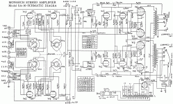
20.5 V from cathodes to ground is across a common 250 Ohm resistor.That means 82mA or 41 mA per tube. 280V x 41mA is 11.5 Watts - You have to get this below 7 Watts.
Before you go to much further check the voltages on the output tube grids. One common problem with these Japanese Amps of this era is that they often used a particular Toshiba Oil Impregnated Coupling Capacitor. These caps dry out and go leaky. This can cause the Output Tubes grids to be pulled positive (as the 0.047uF coupling caps get leaky) and so the tubes conduct excessive current.
I have a STAR SA30 which looks very much the same as far as the schematic goes - I found more than half of those Toshiba Caps I checked were bad. In the end I stopped testing them and replaced the lot.
If the coupling caps are OK then you could try changing the 250R cathode resistor to 270R or even 330R. Note that the cathodes of the two channels are tied together (The "To K1" and "To K2" lines). Again this was not unusual in these amps. You will have to change resistors for both channels at one time.
Cheers,
Ian
Cheers,
Ian
All caps have been changed in the unit so I hope that they are not giving the trouble. Now to find 3 watt resistors in the range that I am looking for. The ones there now are quite large in physical size and marked 3L.K.250ohm suzukiohm and are wirewound.
Will let you know how it goes.
Will let you know how it goes.
- Status
- This old topic is closed. If you want to reopen this topic, contact a moderator using the "Report Post" button.
- Home
- Amplifiers
- Tubes / Valves
- Bias adjustment question