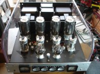
Hello Day, would you mind to share the schematics for this amplifier? i'd like to build it.. thanks!this is my finish PP GM70. I use 5751 for pre and phase st 5687 for drive sound is very good
DAY
")
My GM70 Class A PP - a different design
Hi All,
VERY nice amps day! I've been working on a PP GM70 class A amp now for a couple of months and have purchased most of the parts. Until I stumbled upon this today I have never seen a schematic for a push-pull GM70 amp. I based my circuit topology on some PP circuits designed for tetrodes or pentodes and eliminated the UL tap.
One interesting aspect of my amp will be a solid state phase splitter. The reason I chose this route was that I can build a SS phase splitter with near perfect 180 degree phase across the entire audio spectrum with almost zero shift. The signal is amplified to the proper drive voltages for the GM70s by subsequent 6SN7 driver stages. The phase splitter will be extremely high quality - equivalent to a wire with gain. OPA134s will be used.
I am still debating on whether to go with a fixed grid bias, or, use of a CCS on the cathodes of the GM70 to linearize the performance. I've had great success with self inverting push pull power stages and constant current sources for biasing. I have a high voltage CCS designed that can handle the voltages and currents required. I tested it on a KT88 based PP class A amp with great success. The only drawback is it puts a SS device in the signal path. However, the distortion figures will drop as the tubes will be forced by the CCS to have very symmetrical (yet 180 out of phase complimentary) outputs.
I will post a couple of circuit variations when I get a chance. I would appreciate ANY feedback or comments be they positive or negative. I'm not an expert in this field but neither am I a noob. Somebody might catch a mistake that could save me from a lot of wasted time and headaches.
BTW, power trannys for this project may be obtained for about $100 US on ebay from Antek. I picked up a 1600 volt CT 800VA toroidal power tranny for $90, perfect for this amp. I also plan to use switch mode power supplies on the filaments if I decide to use fixed grid bias and ground the cathodes. I already did this with a 300B amp. If you do it right, it works great. Please don't judge SMPS until you've heard an amp that uses them in a proper design. Considering the filament power required by the GM70 (80 watts EACH!) using SMPS instead of regular power trannys saves a lot of space and money. I calculate a stereo PP amp using GM70s will draw about 700-800 watts of power at IDLE, 320 watts of which is just for the filaments. Probably a good amp for use in the winter, but not in the middle of summer here in Nevada. It's a 3 in 1 product: Amplifier, Heater, and Light.
Lastly the OTs. This was the most difficult part to find. OTs for this project will be required to handle VERY high voltages. Without spending a fortune or winding my own I'm going to chance using an off the shelf model from Edcor. It's rated 100 watts, with a 10K primary and a multi-tapped secondary at 4, 8 and 16 ohms. I would prefer a higher primary impedance but that's the highest they make for that size tranny. Connecting an 8 ohm speaker to the 4 ohm tap should reflect 20K to the primary which the tubes shouldn't mind. The only concern is voltage breakdown. The OTs are designed for tubes that don't bias as high and not necessarily for class A operation either. The GM70 characteristics won't allow the plate voltage to go very low before drawing grid current and saturating the tube, and the output voltage swing is superimposed on top of several hundred volts of DC bias. If the primary impedance is 20K, to get 80 watts the tranny will see 1265 VRMS, or over 3500 volts peak to peak. My circuit will only deliver about 2400 volts peak to peak, or about 850 VRMS. This will translate into about 36 watts per channel (class A). If the primary is 10K (8 ohm speaker on the 8 ohm output) the power goes up to 72 watts per channel. This may or may not provide acceptable performance and distortion levels. With a CCS on the cathodes to bias the tubes it will probably drive a 10K load. With fixed bias and grounded cathodes the distortion may be unacceptable. Experimentation will determine the final design.
More to follow...
I'm looking forward to seeing more ideas popping up on this thread. I've been thinking of a GM70 PP myself for a while. Though now I might use the SV811 series now as the environment I intend to run my amp in does not need the extra heat or power GM70's produce.
sampleaccurate- regarding to OT- I am using an Edcore 10k 100W unit myself (thanks Wavebourn!). One thing I did while breadboarding an GM70 PP amp was to use a bi-polar power supply for the HV; feeding + to the anode circuit and - to the cathode side. Though this does mean the heater supply needs to float and some other things to reconsider, it does make one able to use more off-the-shelf parts. It also alleviates some of the HV worries on the OT.
Thread-
http://www.diyaudio.com/forums/tubes-valves/158769-amplifier-burning-man.html
Much has changed (chip driver probably will go and my initial power measurements shown were off by half) but it gives the basic idea. I feel a little safer being around 600V rather than 1200V!!
-Kent
I'm looking forward to seeing more ideas popping up on this thread. I've been thinking of a GM70 PP myself for a while. Though now I might use the SV811 series now as the environment I intend to run my amp in does not need the extra heat or power GM70's produce.
sampleaccurate- regarding to OT- I am using an Edcore 10k 100W unit myself (thanks Wavebourn!). One thing I did while breadboarding an GM70 PP amp was to use a bi-polar power supply for the HV; feeding + to the anode circuit and - to the cathode side. Though this does mean the heater supply needs to float and some other things to reconsider, it does make one able to use more off-the-shelf parts. It also alleviates some of the HV worries on the OT.
Thread-
http://www.diyaudio.com/forums/tubes-valves/158769-amplifier-burning-man.html
Much has changed (chip driver probably will go and my initial power measurements shown were off by half) but it gives the basic idea. I feel a little safer being around 600V rather than 1200V!!
-Kent
I like the idea of the Op-amp driving a step-up splitter however I wouldn't use a power op-amp. It's not only about the grid current but also the high capacitive load from those power tubes (it is multiplied by the turn ratio!) which has a lot of bad influence on the sound although it can electrically work....
Using chips for driving 150-600 ohm or more, a lower turn ratio and a second voltage gain stage + direct coupled follower is more promising for me.
I think I will try something like this soon...
A good voltage amplifier (with reasonably low input capacitance) + mosfet (tube) source (cathode) follower don't increase the power consumption so much.
No idea about the switching supply for the filaments but your point is good and I wouldn't worry about the purists.....
However I have never been attracted by the GM70 exactly for this reason. Overall it is an inefficient device and I very much prefer the 211/VT4-C.
The Chinese Valve Art and Golden Dragon (copies of the GE design) are quite good and affordable.
45
Last edited:
Looks like a great idea
Hmmmm. That's very interesting. I've never seen this power supply scheme before but it looks like it would work. I'll have to make some changes, but it looks like a good idea. I need to mull this over for awhile. Thanks for the idea. You may have just solved my biggest problem. Obtaining the split supply should be easy with a center tapped power tranny. I would need a second voltage source for fixed grid bias anyway.
Point well taken concerning the ability of a chip amp to drive a coupling transformer. I was actually thinking of building two op-amp preamps, one inverting and one non-inverting, placed at the input, and then amplifying each signal up to the required drive voltage (about 240 volts peak-peak I calculate) using an additional driver tube for each GM70. There are so many different possibilities I've kicked around I don't know where it will end up but this split power scheme looks very promising.
I'm looking forward to seeing more ideas popping up on this thread. I've been thinking of a GM70 PP myself for a while. Though now I might use the SV811 series now as the environment I intend to run my amp in does not need the extra heat or power GM70's produce.
sampleaccurate- regarding to OT- I am using an Edcore 10k 100W unit myself (thanks Wavebourn!). One thing I did while breadboarding an GM70 PP amp was to use a bi-polar power supply for the HV; feeding + to the anode circuit and - to the cathode side. Though this does mean the heater supply needs to float and some other things to reconsider, it does make one able to use more off-the-shelf parts. It also alleviates some of the HV worries on the OT.
Thread-
http://www.diyaudio.com/forums/tubes-valves/158769-amplifier-burning-man.html
Much has changed (chip driver probably will go and my initial power measurements shown were off by half) but it gives the basic idea. I feel a little safer being around 600V rather than 1200V!!
-Kent
Hmmmm. That's very interesting. I've never seen this power supply scheme before but it looks like it would work. I'll have to make some changes, but it looks like a good idea. I need to mull this over for awhile. Thanks for the idea. You may have just solved my biggest problem. Obtaining the split supply should be easy with a center tapped power tranny. I would need a second voltage source for fixed grid bias anyway.
Point well taken concerning the ability of a chip amp to drive a coupling transformer. I was actually thinking of building two op-amp preamps, one inverting and one non-inverting, placed at the input, and then amplifying each signal up to the required drive voltage (about 240 volts peak-peak I calculate) using an additional driver tube for each GM70. There are so many different possibilities I've kicked around I don't know where it will end up but this split power scheme looks very promising.
Different Schematic
Here's my latest GM70 PP circuit adapted to use a split supply. Does this look like it would work? The phase splitter us at the input, using audio op-amps that are extremely quiet with distortion below measurable limits. The drivers are shown as triodes but they may be changed to a triode with an active load (SRPP) or a pentode. I need about 250 volts peak to peak to make certain the power section can be driven to full power without the drivers overloading. The 25 ohm pot is used to balance the bias current to split equally between the tubes, about 90mA each.
The caps between the phase splitter op-amps and the driver grid have been eliminated so there will be only ONE cap in the signal path. Any more excellent suggestions out there?
An externally hosted image should be here but it was not working when we last tested it.
Last edited:
Correct
You are correct about the power dissipation. The circuit I came up with uses an LM317 as a CCS, and a BUX85 transistor is used to keep the voltage on the LM317 within its tolerance limits. The BUX85 can handle 450 volts on the collector and can dissipate 40 watts max. If it's well heat sinked 20 watts should be no problem. I already built this and tested it and it works.
The 1 ohm resistors make measuring the cathode currents easy. 1mA = 1 volt. The LM317 CCS is adjusted to sink 180mA and the 25 ohm pot is used to balance the currents at idle in the tubes.
Looks like an interesting idea!, but make sure that the CCS can dissipate the required power (20 ... 25W if I calculated it correctly).
Kenneth
You are correct about the power dissipation. The circuit I came up with uses an LM317 as a CCS, and a BUX85 transistor is used to keep the voltage on the LM317 within its tolerance limits. The BUX85 can handle 450 volts on the collector and can dissipate 40 watts max. If it's well heat sinked 20 watts should be no problem. I already built this and tested it and it works.
The 1 ohm resistors make measuring the cathode currents easy. 1mA = 1 volt. The LM317 CCS is adjusted to sink 180mA and the 25 ohm pot is used to balance the currents at idle in the tubes.
An externally hosted image should be here but it was not working when we last tested it.
Hi gentlemen,
After some more experiments, I ended up using this schem. Any ideas?
After some more experiments, I ended up using this schem. Any ideas?
An externally hosted image should be here but it was not working when we last tested it.
Hi gentlemen,
After some more experiments, I ended up using this schem. Any ideas?
I like it!
Why didnt you use grid stoppers on V4, V5 and V6 ?
Also, i'd change the bias circuit (the pot meters) so that when one breaks (wiper loses contact) the voltage goes all the way down, and not to 0V
Last edited:
Thank you hidnplayr for your comments.I like it!
Why didnt you use grid stoppers on V4, V5 and V6 ?
Also, i'd change the bias circuit (the pot meters) so that when one breaks (wiper loses contact) the voltage goes all the way down, and not to 0V
I actually use grid stoppers for V5 & V6 (forgot to put them in the schematic). For V4 I think R8 already works as gird stopper, so no need for that.
Havent thought about the pots, talking about changing bias circuit, did you mean changing R27, R28 value and connect them to B-?
Thanks again.
Last edited:
Havent thought about the pots, talking about changing bias circuit, did you mean changing R27, R28 value and connect them to B-?
Thanks again.
I was thinking something like this:
Attachments
measuring cathode current over the 1 ohm resistor: 1mA = 1mV (not 1V).
Pieter
Sorry - typo.
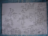
GM70pp class A driven by RY50 SRPP and 6SN7
Hi, this is my GM70pp 80W per channel, class A amp that is powered by a pair of modified ISCO 494 power supplys (1100V 300mA each).
It is using 6SN7, SRPP RY50 pair at 1000V parafeed driving a LUNDAHL 1660PPZ as a phase inverter.
Comments on the schematic are welcome!
adam2a3
Hi, this is my GM70pp 80W per channel, class A amp that is powered by a pair of modified ISCO 494 power supplys (1100V 300mA each).
It is using 6SN7, SRPP RY50 pair at 1000V parafeed driving a LUNDAHL 1660PPZ as a phase inverter.
Comments on the schematic are welcome!
adam2a3
Attachments
Hi Adam,
Nice amp & schem, below are some of my ideas:
- The ГМ-70s and ГУ-50s seem to be too close to each other, with my amp, even though being monoblocks but with total idle dissipation of ~300 W/channel, it's way too hot that you should not use it in summer days
- The OPTs are 10k p-p? From the pictures I think it would be better if those OPTs are bigger.
- The 68Rs at cathodes of ГМ-70 should be 3W.
Regards,
Duong
- Status
- This old topic is closed. If you want to reopen this topic, contact a moderator using the "Report Post" button.
- Home
- Amplifiers
- Tubes / Valves
- want to do PP-GM70