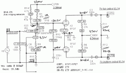
I have build this input stage for my 6L6GC amp (without the antiringing network).
But with different B+ at the phase splitter.
My measurements (hand writing letters) are a little bit different than the schem's.
Do I have problem with these measurements?
But with different B+ at the phase splitter.
My measurements (hand writing letters) are a little bit different than the schem's.
Do I have problem with these measurements?
Attachments
I use 6SN7.Sorry that I didn't mention.It's the same,though.C1 may be leaky or you might have a slightly sour 6CG7.
And it's a new EHX.I have done measurements with other 6SN7s with the same results.
C1 is a new Audyn MKP cap.So,....
Very interesting!edit: DUH! Or your meter is loading that grid down a bit. That's most likely. Your voltages are fine.
The impedance. The lower grid in the diagram is fed through a 1M resistor. The meter's impedance provides a voltage divider to ground. For the upper grid, the meter forms a voltage divider with only 47K ohms (or so), so it doesn't much perturb that voltage reading. Your meter would appear to have about a 10M impedance.
BTW, to confirm that I was an idiot, connect the meter from grid to grid (i.e., across the 1M resistor)- I bet it reads close to zero volts.
BTW, to confirm that I was an idiot, connect the meter from grid to grid (i.e., across the 1M resistor)- I bet it reads close to zero volts.
- Status
- This old topic is closed. If you want to reopen this topic, contact a moderator using the "Report Post" button.
