I've built an amp but when I fired it up the heater voltages were spot on:5v rectifier(5Z3),2.5v 2A3,6.3v 6sl7.B+ on the other hand is 200v down.I measured the voltage on the tranny 380-0-380 no problem.Same going into rectifier.Measured opt connection to B+.It reads 215v and the HT wiring to rectifier is hot enough to melt solder.Any suggestions as I'm a newbie and lost????????
Its the Morrison Micro circuit I'm building.
Its the Morrison Micro circuit I'm building.
SY said:You're clearly drawing too much current somewhere. Replace the audio circuit with a power resistor
I'm gonna need some help with that please.Every other amp i've built worked ok first go.
SY said:OK, let's take it step by step. What is the B+ supposed to be and how much current is the circuit supposed to draw?
If you've got a link to the schematic, that will help us walk you through the process.
Here's the diagram
Attachments
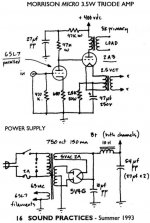
OK, without going through the circuit in detail, one can see that the total draw from B+ will be on the order of 50mA (it might be 40, it might be 80, but we're just approximating). OK, so that means, as far as the power suply is concerened, the load looks like whatever resistance it takes to conduct 50mA (0.05A) at 400V. Pull Ohm's Law out of our mental toolbox: the equivalent resistance is voltage divided by current. So R = V/I = 400/0.050 = 8,000 ohms. So an 8,000 ohm resistor will load down the supply properly (nearest standard values are 8.2K or 7.5K).
Now, we put Ohm's Law back neatly and pull out Ohm's Power Law, power = voltage times current. In this case, P = 400 x 0.05 = 20W. So... disconnect the B+ feed from the circuit, attach an 8.2K (or 7.5K) 25watt power resistor across the power supply output. Check the voltage. If it's 400V like it's supposed to be, the power supply is fine and you need to start troubleshooting the amplifier. Contrariwise, if the voltage is low, then the power supply has a wiring error or a bad part.
Either way, you've cut the problem in half.
kianbach said:PSU filter cap WRONG WAY ROUND.DOH!!
Ummm.....valves/tubes are so forgiving to the greatest mishaps.....that 5Z had to stomach the lot.....you wouldn't have gotten away as-clean-as that with a SMPS....
richj
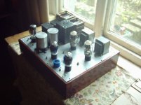
Are those in the foto 6SL7
Nope,the tubes in the foto are ECC32's which are near equivalents to 6SN7.I found that the SL has too much gain.
no hum pot for minimising the hum
If you look closely at the photo you'll see there are 2 humpots between the input and output valves.The 2 big caps between the input alves are the bypass caps for the 2A3 cathode resistors which are connected to these humpots.measured hum is 3mV on each channel.DC filament supply for the input valves consisting of a bridge rectifier and a pair of 22000uF caps with a dropper between them.Totally silent
")
- Status
- This old topic is closed. If you want to reopen this topic, contact a moderator using the "Report Post" button.
- Home
- Amplifiers
- Tubes / Valves
- B+ problem?