Hi,
My first post. I've been looking at the "Five Tube Stereo Amplifier", designed by Wes Kinsler (you can see it at: www.wkinsler.com/radios/5tubeamp.html ). I was thinking of trying to build it without the tone controls but had a few questions. Mr. Kinsler lists the parts required to build the amp but labels the capacitors mF. Does he meen uF (microfarad)? And capacitor No. 5 has a value of mmF? Is this maybe a typo or does he possibly meen pF (picofarad)? If someone can help with this it would be appreciated. Also, any general opinions regarding the design would be great. I can't find a transformer (Hammond or any other) that seems like it would work for the power transformer (600v CT @ 80ma?). Suggestions would be great. I've built the S-5 11MS8 kit and have messed around some with electronics. It would be nice to try to build something simple and cheap for a first amp. Oh yah I built some pretty decent speakers (foxtex FE207E 95/db efficiency).
Thanks in advance. Dylan.
Hi Dylan.
Looked at the schemo and part list, and, yes, mF is for microfarads and mmf for picofarads.
I think there is a typo in that the grid of the first tube is floating.
Since they have the cathode grounded, I suggest to add a 5 to 10 megohms resistor from each grid to ground in order to implement a so called "grid leak" biasing.
Do not simply short the link cap (C1) !
Yves.
Grid Leak Biasing Eh?
Thanks for your replies.
The transformer question has effectively revealed my ignorance so I have nothing to lose. Thanks to Giaime for the transformer information. I looked over the specs of both transformers and the specs on the various tubes and it looks like either one would work fine (and they'll fairly inexpensive too) as Mr. Burns would say "excellent".
Yves,
Grid leak biasing eh? I looked over some circuits that use this and I think I understand you. But lets make sure. I don't have any children (that I know of) yet and I don't want the Snufnerowski name to die out just yet.
This is all very interesting.
Dylan
Thanks for your replies.
The transformer question has effectively revealed my ignorance so I have nothing to lose. Thanks to Giaime for the transformer information. I looked over the specs of both transformers and the specs on the various tubes and it looks like either one would work fine (and they'll fairly inexpensive too) as Mr. Burns would say "excellent".
Yves,
Grid leak biasing eh? I looked over some circuits that use this and I think I understand you. But lets make sure. I don't have any children (that I know of) yet and I don't want the Snufnerowski name to die out just yet.
. I take it we are talking about the 6SF5GT tube? So, to grid leak bias the grid on each of the 6SFGT tubes I would connect a 5 or 10 megohm resister from pin 3 to ground? How would I determine which (5 or 10) megohm resistor to use? Or would it not really matter much? Oh, and what watt resistor would I use? Thanks for your help.The grid of the first tube is floating
This is all very interesting.
Dylan
Hi Dylan,
Yes, you get it.
Use what you have at hand between 5 and 10 M, there are no watts dissipated inside, don't care !
Yves.
So, to grid leak bias the grid on each of the 6SFGT tubes I would connect a 5 or 10 megohm resister from pin 3 to ground? How would I determine which (5 or 10) megohm resistor to use? Or would it not really matter much? Oh, and what watt resistor would I use?
Yes, you get it.
Use what you have at hand between 5 and 10 M, there are no watts dissipated inside, don't care !
Yves.
2 suggestions: first use a 1M metal film 1/4W or 1/8W resistor between grids to ground. 1M and not more because more resistance means more noise with high values. And also doing this you will reduce input impedance (not too much), that will not matter in audio but will in RF in case you'll picking up interference or oscillations. Solder the resistor nearest to the grid pin on the socket.
Second: use the DX tranny. The other one seems a bit underrated for filaments...
Second: use the DX tranny. The other one seems a bit underrated for filaments...
Altered Circuit
Well, here it is. I've altered the circuit to remove the tone controls and included the considerations for grid leak bias and power transformer. I put in the Hammond 125 ESE as the output transformer. If this is not appropriate let me know. The origional schematic called for a prim Z of 7600 Ohms. I figured with the many choices for primary impedance on the 125 ESE, that it would be a good choice. I think I would have to connect wires 3 & 6 to get a Prim Z of 6800 Ohms on the 125 ESE. Hopefully this will be close enough? Let me know what you think about the circuit. thanks for everyones help. Dylan.

Well, here it is. I've altered the circuit to remove the tone controls and included the considerations for grid leak bias and power transformer. I put in the Hammond 125 ESE as the output transformer. If this is not appropriate let me know. The origional schematic called for a prim Z of 7600 Ohms. I figured with the many choices for primary impedance on the 125 ESE, that it would be a good choice. I think I would have to connect wires 3 & 6 to get a Prim Z of 6800 Ohms on the 125 ESE. Hopefully this will be close enough? Let me know what you think about the circuit. thanks for everyones help. Dylan.
Altered Circuit
Well, I tried to attach the circuit to the last reply and it doesn't appear as if that worked very well. I'll try to convert the file to another format and attach again. Here goes:

I converted the image to a jpeg image. Hopefully that will work. If you can open it please let me know what you think. Cheers.
Dylan
Well, I tried to attach the circuit to the last reply and it doesn't appear as if that worked very well. I'll try to convert the file to another format and attach again. Here goes:
I converted the image to a jpeg image. Hopefully that will work. If you can open it please let me know what you think. Cheers.
Dylan
Built it!
Just finished building this amp , and I have been listening to it all day, cant stop! This tube amp should be more popular than it is, I was half expecting it to suck due to the schematic's lack of feedback from others, but man, i'm glad to have built it anyway.
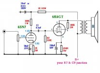
I traded the two input tubes for a single 6SN7 (it has two triodes in it, and has a much better reputation). Rather than using the power supply resistor R9, i used a 15H choke for better regulation and efficiency, and rather than two 10uF supply caps C6 and C7, i used a 15uF before the choke, and 40uF after it. Both my supply caps are big old oil capacitors at 450V. Everything else is the same from the schematic. I highly recommend the choke and the oil caps.
My power transformer is 95VA and still gets quite hot, i had to thermal epoxy some heatsinks to it. The output transformers should be as big as possible for better bass.
I also built an LM3886 chip-amp by carlosfm's schematic (also amazing) and I don't know wich is better. This tube amp definitely easier to lisen to at the end of the day sometimes. Its so warm and airy, even sounds good with mp3 files (unlike the chip amp).")
There really aren't any problems, this is the first of 4 amps i've built that didn't begin with noise that needed to be diagnosed right away. There's no noise and no clear frequency aberrations.
I have noticed that it doesn't like metal too much, like, metallica sounds better on my chip-amp. But test it out with Jack Johnson, and you'll have a hard time turning it off.
Just finished building this amp , and I have been listening to it all day, cant stop! This tube amp should be more popular than it is, I was half expecting it to suck due to the schematic's lack of feedback from others, but man, i'm glad to have built it anyway.
I traded the two input tubes for a single 6SN7 (it has two triodes in it, and has a much better reputation). Rather than using the power supply resistor R9, i used a 15H choke for better regulation and efficiency, and rather than two 10uF supply caps C6 and C7, i used a 15uF before the choke, and 40uF after it. Both my supply caps are big old oil capacitors at 450V. Everything else is the same from the schematic. I highly recommend the choke and the oil caps.
My power transformer is 95VA and still gets quite hot, i had to thermal epoxy some heatsinks to it. The output transformers should be as big as possible for better bass.
I also built an LM3886 chip-amp by carlosfm's schematic (also amazing) and I don't know wich is better. This tube amp definitely easier to lisen to at the end of the day sometimes. Its so warm and airy, even sounds good with mp3 files (unlike the chip amp).
There really aren't any problems, this is the first of 4 amps i've built that didn't begin with noise that needed to be diagnosed right away. There's no noise and no clear frequency aberrations.
I have noticed that it doesn't like metal too much, like, metallica sounds better on my chip-amp. But test it out with Jack Johnson, and you'll have a hard time turning it off.
That was the FIRST amp I ever built....HATED IT!
I then REBUILT it using a 12AT7 up front and 6V6's for Output.
I used 5K OPT's (6800 will be better)
I eliminated the tone controls and went to Cathode bias on the 12AT7.
That amp was the one that got me into tubes!
As drawn I was not real happy with any of it, but the learning experience with a BASIC circuit was well worth it.
The PS as drawn is pretty noisy.
Here is a tip I got from a user on here.
Get a copy of a tube manual (I recommend RC-30) I think Pete Millet has a downloadable PDF on his site but just "GOOGLE RC-30 Manual"
Read the sections on Class A amps and Resistance Coupled amps.
Like I said before building this as a "first amp" is OK but I would recommend "learning" a little before hand. You seem to be well on your way.
As a relative "NOOB" myself I found out the hard way that just copying a schematic "by the seat of the pants" is an easy way to get frustrated or hurt.
Wes Kinsler has some nice stuff on his site but his " tube substitutions" leave little explanation. The ideal operating points will become more apparent if you read the tube manuals.
I am not sure of your "tube selection" or if you have any at all.
Email me if you need a copy of RC-30 I have one broken up into small PDFs. I can also offer advise from "NEWBIE" to NEWBIE
Jaencer,
Email me and I will work up a quick schematic to run the 6K6's "triode" strapped. SET is the best sound your gonna get from that tube lineup.
Depending on your source we might want to stay with the SN7's they are SWEET as far as sound and linearity.
This schematic has lots of gray areas and we can improve on it and simplify it a lot.
coldcathode said:I then REBUILT it using a 12AT7 up front and 6V6's for Output.
Everyones always talking about 6V6 tubes... maybe they'll work better. thank god those tubes are cheap
coldcathode said:jaencer,
The 6SL7 has a a Mu of 70 the SN7 Mu of 20 so the gain is MUCH larger with the SL7.
You built it to the schematic using a 6SN7 correct?
Yes. Actually a 6SN7GT tube (my dad said it would be silly to use anything else, guess he paid a lot for it). I have noticed the low gain-- the vol. knob is always at like 85% for listening :/ BUT maybe changing the output tubes to 6V6s would increase the gain???
coldcathode said:Jaencer,
Email me and I will work up a quick schematic to run the 6K6's "triode" strapped. SET is the best sound your gonna get from that tube lineup.
Depending on your source we might want to stay with the SN7's they are SWEET as far as sound and linearity.
'triode strapped' [searches wikipedia for a while] dude this could work, this would get rid of the feedback, right? And would make better use of the HUGE output x-formersI'll email you, thanks so much.
nice schematic! even the pinouts
sry for all the questions, but
- there's no input cap! that works with tubes?
- any value vol. pot? (10k instead of 1M is good?)
- will this new schematic have less output power than the original?
(it certainly looks more reasonable with the values-- seriously, that 4.7nF input cap is a relief to be rid of)
No need for the cap if there is no DC on the outputs of the source. I assume there is no Tube Preamp? Just a CD player or something.
You can use any value for the Volume depends on the source. I often use a If your source has a Volume control like a PC or Ipod you could eliminate the cap and use a 220K resistor.
Yes, This will have less power than the other. Don't get hung up on wattage. If your speakers are reasonably sensitive 88db or better you should be able to hear it just fine.
If you plan on doing much with tubes some 8ohm 90db or better speakers are a must.
The distortion on this will be pretty high, mostly a factor of the high output impedance and low Plate Voltage and Current.
Give me more info on your power tranny and maybe we can boost power up a bit and bring the distortion down. I was trying to stay within the limits imposed by the original schematic.
The 5 tube amp suffers from very restricted bandwidth, most likely the reason the "metal" doesn't sound so good.
I listen almost EXCLUSIVELY to MP3's thru my 6V6 PP amp. It is relatively easy to build also. It uses similar tubes, send me an email and I will email the schematic. It is right up your alley for your next project. 8-9watts per channel, 7 tubes.
The 6SN7 is a great tube, I happen to like its "younger brother" the 6CG7/CFQ7.
Triode Strapped is simply using the Pentode as a Triode by tying the Screen Grid to the Plate.
NEVER APOLOGIZE for asking questions! The only time to apologize is if you ask the same question twice.
- Status
- This old topic is closed. If you want to reopen this topic, contact a moderator using the "Report Post" button.
- Home
- Amplifiers
- Tubes / Valves
- Has anyone built this amp?