exurbia said:The beer midget (my lovely other half) has said either they go or she does. I told her how much i'd miss her and that i respected her decision.

exurbia said:What to do ??
Send this way for safe disposal! (the amps, not the wife
)But seriously, they look like they may really be worth saving. The big, heavy transformers alone indicate that they may well have been high quality amps in their day. Can nothing be done to dress them up to increase the spousal acceptance factor?
Spousal acceptance is not too difficult, she already lives with speaker baffles that are floor hungry. The amps may be worth saving but rejuvenating them is too time consuming for me. My original plan went something like this.
1 Find someone willing to do a rebuild/repair
2 Pay them for their services
3 Pay them either with money or kind ( i have a vast collection of valves etc,etc.
As we live in the nor west, freight cost would kill the transport of the whole lot.
Plan 2 is
1 find someone who can test and configure the output trafos then i could cajole my son into doing the rebuilds.
It may be possible for you to determine the connections of the output transformer yourself.
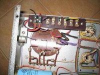
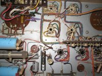
Looking at the last picture you posted, pin 4 (the screen grid) on all valves is connected to the solder tag in the middle - this suggests they're configured in fixed screen mode, rather than ultralinear. The yellow wire on the left sockets, and the blue wire on the right sockets are the anodes of the valves, and these would be going to each end of the primary winding of the output transformer. The connection between the output transformer and the power supply will be the centre tap of the primary.
Determining the secondary connections won't be quite so easy. Sections of the transformer which measure <1W DCR with a multimeter are likely to be secondary connections. Applying a known AC voltage across the primary and measuring the resultant voltage across the secondary will allow measurement of the turns ratio, and the derivation of the impedance ratio as the square of the turns ratio.
Sorry I can't be more helpful, it's a little hard trying to explain these things in words.
Thanks everyone
Restoring these t the original condition is not what i had in mind.
Plan 3
1 use the amps but set up for class a operation
2 put the chassis into a nice frame/plinth
3 listen
4 become a convert to valve power amps
5 stick with my HE setup
At the moment i use a valve pre with big big solid state amps the whole set up is active using a behringer ultradrive pro and 2496 ultracurve. The system has plenty of headroom as it uses pro audio drivers .
It would have been nice to see them restored. Oh well.
Trying to describe how to redesign these amps is probably a bit much to try and explain on a forum. I could try, but I don't think I'd be very successful...
The ideal situation is where you'd be able to do it yourself after reading a book or two, but that's going to take up quite a bit of whatever spare time you have...
Hmm...
Jason, thanks for your time and smarts. The guy i got these from tells me they were set up for class B. They wanted as much power as possible for the field arrays.
After reading through many of the posts in 'tubes' i had come to the conclusion that class A was the way to go with them. Any suggestions are welcome but doing the rebuilds is beyond my ken. I can follow instructions and swap components. My field is high power locomotive and marine engines, i build speakers for a hobby and usually buy my electronics ready built. The exception is building other peoples designs, like i said i am good at following directions and doing a bit of design.
After reading through many of the posts in 'tubes' i had come to the conclusion that class A was the way to go with them. Any suggestions are welcome but doing the rebuilds is beyond my ken. I can follow instructions and swap components. My field is high power locomotive and marine engines, i build speakers for a hobby and usually buy my electronics ready built. The exception is building other peoples designs, like i said i am good at following directions and doing a bit of design.
Hi exurbia,
Too bad you can't hide 'em. I'd rebuild them and listen (start with one). You can increase the plate current to normal levels for the plate voltage and listen again. If you like, fix the rest and mount out of sight. I think that is the biggest problem with the WAF. I got me one too and we co-exist. Good thing she really likes music!
-Chris
If the amps are running in class B, the HT voltage will probably be quite high, and the idle current quite low (to remain within anode dissipation ratings). If you're wanting to modify them into class A, you will have to significantly increase the idle current. Thus, to remain within ratings, one would have to either change to valves with a higher anode dissipation rating, or lower the HT voltage. Having a quick look ot one of the pictures you posted, it seems the power transformer has multiple taps, so the latter option is likely more viable since it won't introduce as much additonal heat into the space on the chassis between the OPT and power tx.
However, instead of going the PPP pentode route, since the KT66 can handle quite a few volts on the screen, have you considered PPP triode connection?
However, instead of going the PPP pentode route, since the KT66 can handle quite a few volts on the screen, have you considered PPP triode connection?
Jason,
I would consider anything, even putting my DA42 triodes in if that were possible.
The beer midget understands the need for amps, she just has problems with the quantity that we have.
I would really like to see these running again and to hear them. Beer midget has suggested selling one with the remaining KT66 quad, and using the funds to pay for the restoration of the others.
High Quality amps
IMNSHO, these are clearly high-quality amps. The construction level speaks to that, definitely cut of the cloth ala Western Electric and the like. They didn't do anal wire lacing like that on cheap crappy amps. also, the size of the iron speaks to the quality. and KT66s were not something commonly specc'ed.
amps like these deserve to be restored before doing anything else with them. If you need/want to hack on something and get your feet wet, find something else or buy a bottlehead kit or something. Don't trash a great set of amps like these. nothing you could do them from a diy/hacker standpoint would improve their value or likely even their sound.
Old thread indeed
I would like to see if it can be livened up again as there has been some progress on these amps so your kind answers did not go to waste
So here is the state of play so far
I bought these 3 amps from Exurbia some time back
The certainly looked better in the pictures when listed on eBay When they did arrive and after a close examination I decided that they needed a lot of time spent on the which was not available back than so they just where sitting around
Two weeks ago I dusted them down and started drawing out a schematic following the construction tracing each and every connection wires measuring as well as deciphering components etc we all have done that I am sure some of you know what a pain it is
Quite a job correcting mistakes and all of that I am sure its all correct now so once it is laid out nicely I will post it as it is a bit of a mess to post it up now
I am now at the stage where one of these amps has been checked components gone bad replaced some Russian KT66 equivalent tubes fitted with some 6SJ7
The amp was fired up through a variac slowly bringing current up to full over a day or so while doing other things at work Did not want to clean up electro gung I am sure some of you have seen it firing up old gear
After some more component replacements it all seems to be holding together nicely
Having been on idle at full current for about 2 odd days 8-10 hours per day it appears that it will be a OK
The components new and old seem to be fine with the main transformer just getting warm all else seems to be OK
I have yet to put a signal through it as
There are two issues that need addressing:
1.I am having some output transformer uncertainties
The plates of the four output valves do go to the primary a pair of valves per side 2 windings with supply in the CT
The secondary is multi wound with what appears to be 5 individual windings
I have yet to find any information on these Ferfuson transformers after numerous searches
The part number on them is OP 527 No old catalogues of the maker lists them as I have found more than one of these
So since there are a couple of Aussies here they may be able to have a dig around Hopefully!
The alternative of course is to apply a known AC on the primary and see what the ratio is as already suggested here
It would be nice to know what the specs of the massive transformer are
As for the rest it seems to be a rather interesting design with massive chokes & transformers
No issue with the power supply transformer all simple and easy but the output has me a bit baffled so unless I can get some specs on it I will have to do it the hard way
The primary measures 45.7 Ohms on one side and 53 ohms on the other side So it has me a bit curious as for such a well made transformer it should not have this much variation if it is indeed centre taped
May be after it has run for a while it may settle down but after 2 days on power it should have done so if this was the case I was thinking moisture not enough to cause a short but enough to read wrong
Not the case so far It may be early days? I am not sure but I have seen this before where old gear fired up settles down after a few days running Since these amps have not been fired up for 30 years or more it may be the case
The other side the secondary has 5 windings 4 of them show a resistance of under one ohm each .8 to be precise with the last one indicating 1.6 ohms
Hooking them all together in series I get 4.8 ohms
Arguably this should be enough to either use 4 Ohm impedance speakers or 8 ohms in parallel
But I would be happier to get the specs at this stage
2nd Issue:
The 6SJ7's drivers for the output valves seem to be within the specs running conservatively at 190V anode supply from a 320 V rail so It seems OK as is also the bias on idle
I suspect that the first 2 valves on the signal input side fed from the input transformer may be other than 6SJ7's
They run at a much lower anode voltage under 100 V and the filament voltage is also under half of the 6.3 V filament voltage required by the SJ's
The filament current is set via a w/w variable resistor at 2.87 V AC
I am quite or very rusty on audio valves as well as valve types even though I grew up with them but mostly for RF rather than audio
I was hoping that once the schematic is posted I would be very pleased of any suggestions to the contrary or what may have been used for the first two valves
Lastly
I could not find any information on these amplifiers any where searching and scratching around
After many searches I did come across this thread Joined the forum and it did gave me enough information to be able to get so far
To get the other two going would be a walk in the park by comparison as this has taken the best part of 12-14 x with some 12 hour stretches
All for the love of it? I think it would be a Good result
BIG Thanks for your input so far it has been a great help to me at least, even though it was started by the original guy
Best
Chris
You seem to bee too much concerned about transformer "specs" in a well designed and (presumably) working piece of equipment. Some variations like the one you noticed, do happen (half of primary is would over the other half, requiring more magnet wire for example). If the transformers in the other amps are dead, any competent winder can reverse engineer them and rewire them.
As you said, the best way to determine how connect your speaker is to apply a known AC and note the impedances.
By the way, hope you did not run it all that time without any load.
As you said, the best way to determine how connect your speaker is to apply a known AC and note the impedances.
By the way, hope you did not run it all that time without any load.
Hello
I am looking for the right specs Not really concerned As already pointed out there are ways around it
There is a "dummy" load already at the end of the chain 10 ohms with about 250 Watts dissipation So no big deal
There is only DC flowing any way so since no modulation is taking place, no harm any way as there is nothing induced on the secondary side
May be a bit of saturation on the transformer but thats about
It will not get magnetized so as to cause problems at a later stage even without a load the secondary
A simple check with an ohmmeter and a mega indicates good transformers on the other two amps
These are really heavy duty built weighing about 6-7 KG each as an educated guess they will take a lot of killing
Thanks for the input
Yia Sou
- Status
- This old topic is closed. If you want to reopen this topic, contact a moderator using the "Report Post" button.
- Home
- Amplifiers
- Tubes / Valves
- cinema amps