I have seen CAE upgrade for MARK III using 2- 6922s. This would be certainly one of my option. I am now on the drawing board laying out the parts and the chassis. I have 6550s and KT88s power tubes to try along with my 6SN7s as drivers. 6922s are not so expensive, i can get four of them soon..now my jensen imperials are waiting for this amp to drive them. certainly hope i can finish them soonest time possible!
If you use this board (CAE) you can drop in 6CG7's in place of the 6922's. personally, I like the sound of the 6CG7's better. The 6922 / 6DJ8 tubes sound a little on the harsh side in this application.
And don't worry about the 6CG7's lower gain. In this circuit the 6CG7 will still have more than enough gain to drive 6550 / KT88's. In fact, I use this board with 6CG7's to drive a 6SN7 cathode follower which drives PP 6B4G tubes in PP class "A" with plenty of drive to spare.
Daniel
You can also use 6SN7's in place of the 6922 / 6CG7 in this circuit with rewiring for the 6SN7's different base. The great thing about this circuit is that it is not too particular with tube changes and still performs excellently.
This circuit originally was in Wireless World in the mid 1950's; Curcio basically copied it and gave it some modern tweeks.
Last edited:
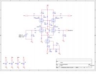
I think PSpice and LTSPice are trustworthy, but I kind of have a funny feeling about this. All similar designs have higher B+ voltages than mine. If I go any higher, the power goes too high. What do you guys think? Should I go ahead and build this circuit, or should I investigate further?
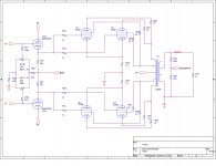
The output transformer is a 1.9k in the primary and can handle up to 130 watts RMS.
your schematic shows a 1650r output transformer. If thats a hammond 1650r, the impedeance should be 5K and handles 100 watts rather than 1.9k handling 130 watts.
That is a Typo, the transformer is custom wound for 1.9k ohms 130 watts.
so the computer modeling wasn't based on a 5k tranny........ok
http://www.diyaudio.com/forums/atta...113191450-dynaco-120w-amp-dyna-451-dud120.pdf
The 10R 0.25W cathode resistors in the o/p stage are hopelessly underrated.....they will go "high" on an impulse transient. I used 10R 3W Dales. However it looks by the values in your schematic that slewing will be early. If you want a good topend response then the 4K7 output stage grid resistors will have to be reduced to 1K. A squarewave shows diagnostic wonders. The 1K Zobel snubber, a 3W rated is correct with on a 100W amp driving a difficult load esp a piezo tweeter.
Strickly parallel p-p pairs needant use a cathode follower. The only current Miller dump on turn off is that slow 47K (R105-106) cathode resistor and this is often too slow. I much prefer to use an active push pull driver as this guarantees bandwidth.
Although MJ book "valve amps 4th ed" Crystal palace amp p.478 uses a cathode follower for the o/p stage, it is current forced with a neg supply.
I found very early on, testing tube amps at high audio frequency & power will TEST the design and the components and 100W at 15KHz won't be a breeze without smoke !
richy
The Hammond 1650R quotes -3dB at 30Khz.......this can't be right. As a custom wind, do you have another quoted figure for the top end droop ? I would be expecting a min -3dB at 50Khz....If they insist at 30Khz then there's no point going into a high performance driver.
richy
richy
The transformer is flat from 20-20kHz. The break points are unknown.
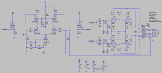
Anyway, I made a change to the driver so the output tubes are directly coupled to the cathode followers. A simple cathode follower you said will cause slew due to the large resistor, and that Morgan Jones solved that problem using a negative voltage supply on the CF. Will the change I made fix the slew problem?
Anyway, I made a change to the driver so the output tubes are directly coupled to the cathode followers. A simple cathode follower you said will cause slew due to the large resistor, and that Morgan Jones solved that problem using a negative voltage supply on the CF. Will the change I made fix the slew problem?
Attachments
Last edited:
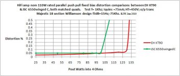
Reverting to previous posts, I notice your B+ around 500V for 100W. I'm using KT90's parallel p-p at 455V and getting a notch 120W at a better quality than the 6550/KT88 bunch giving around 100W. The advantage with KT90's is the quiescent can be increased giving a slam top end performance. Amplifiers of this nature have an excellent risetime and considered "bright" on the strings. With 575V B+, the above cue can reach 200W o/p and this level at 10Khz requires some care. This implies peak transient currents can be quite high, hence my remarks about those o/p stage cathode resistors be able to take impulses.
My "slaughter" driver approach is different using 12BY7A video tubes,(cct will come later) although later modified to take other tubes. It is unslewed and envolved considerable midnight oil..getting it right. The amp circuit aka Williamson is dependant on a top flight o/p transformer with -3dB 70Khz and this isn't cheap.
Reverting to previous posts, I notice your B+ around 500V for 100W. In one amp, I'm using EH KT90's parallel p-p at 455V and getting a notch 120W at a better quality than the 6550/KT88 bunch giving around 100W. The currently made KT88's around aren't road worthy. An advantage with KT90's is the quiescent can be increased giving a slam top end performance. Amplifiers of this nature have an excellent risetime and considered "bright".
With 575V B+, the above cue can reach 200W o/p and this level at 10Khz isn't trivial and care has to be taken.
Is different and presents more of a challenge. At these power levels, Pspice cannot predict output transformer characteristics and using a top flight o/p transformer with -3dB 70Khz is worth reaping the rewards. The main power supply has to supply the goods 575V at 1A with no droop; PLUS the heater current spec'd at 25A. At 575V, the SS PFC comes to the rescue, hence a raft of protection is also required.
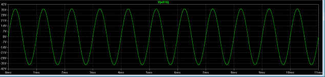
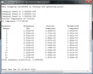
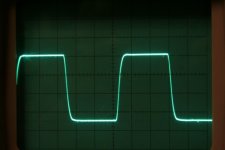
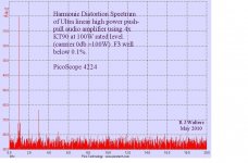
A pic of the squarewave at 100W level + power comparisons. Notice f2 on the spectrum has fallen quite low.
Those advocates who "hate" EH KT90's will be pleasantly surprised how these amps can sound and have quite a smooth spectrum.This is one of my designs that ended up in recording studios. It isn't an MI amp, but often gets used for such.
Those wanting real tube power game, one is in for shock what such amps can perform.
richy
My "slaughter" driver approach is different using 12BY7A video tubes,(cct will come later) although later modified to take other tubes. It is unslewed and envolved considerable midnight oil..getting it right. The amp circuit aka Williamson is dependant on a top flight o/p transformer with -3dB 70Khz and this isn't cheap.
Reverting to previous posts, I notice your B+ around 500V for 100W. In one amp, I'm using EH KT90's parallel p-p at 455V and getting a notch 120W at a better quality than the 6550/KT88 bunch giving around 100W. The currently made KT88's around aren't road worthy. An advantage with KT90's is the quiescent can be increased giving a slam top end performance. Amplifiers of this nature have an excellent risetime and considered "bright".
With 575V B+, the above cue can reach 200W o/p and this level at 10Khz isn't trivial and care has to be taken.
Is different and presents more of a challenge. At these power levels, Pspice cannot predict output transformer characteristics and using a top flight o/p transformer with -3dB 70Khz is worth reaping the rewards. The main power supply has to supply the goods 575V at 1A with no droop; PLUS the heater current spec'd at 25A. At 575V, the SS PFC comes to the rescue, hence a raft of protection is also required.
A pic of the squarewave at 100W level + power comparisons. Notice f2 on the spectrum has fallen quite low.
Those advocates who "hate" EH KT90's will be pleasantly surprised how these amps can sound and have quite a smooth spectrum.This is one of my designs that ended up in recording studios. It isn't an MI amp, but often gets used for such.
Those wanting real tube power game, one is in for shock what such amps can perform.
richy
Attachments
- Status
- This old topic is closed. If you want to reopen this topic, contact a moderator using the "Report Post" button.
- Home
- Amplifiers
- Tubes / Valves
- DYNACO 120W AMP for DYNA A-451