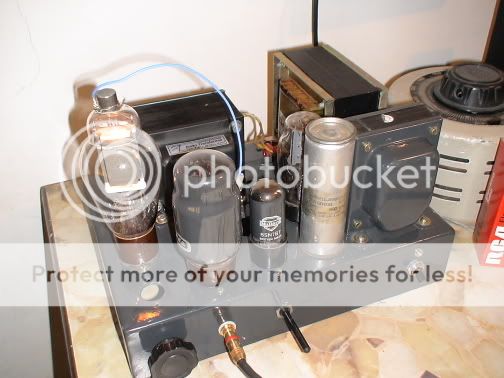
Attached a pic of my ‘Mil’ spec prototype employing the chassis and PSU Choke from an abandoned 807PP project.
The main B is now at 550volts. Sounds more open. Kick drums and snarls have greater slam. Highs are as usual crisp. I can’t attribute the precise reason for this improvment. Cold be due to the higher B or maybe after 30+ hrs the everything is coming together for a synergetic blend. All components were absolutely new out of the box.
RCA 811, Mullard 6SN>, GEC KT66, Mulllard GZ32. I final build I will replace the KT66 with a 807 or 307A. Mainly due to fact that I am cheapster; but also them top caps will look cool next to the each other")
AC Heating:
From my listening position, I can’t hear any hum. So that is good enough for me. But I may go in for separate filament transformer in my final build. I am noticing some kind of rectification noise (???) and expect independed fill tranny to quitent this noise (sounds more like SS diode swicthing noise) a better job. DC is ruled out.
Still no measurements. Maybe this weekend.
The main B is now at 550volts. Sounds more open. Kick drums and snarls have greater slam. Highs are as usual crisp. I can’t attribute the precise reason for this improvment. Cold be due to the higher B or maybe after 30+ hrs the everything is coming together for a synergetic blend. All components were absolutely new out of the box.
RCA 811, Mullard 6SN>, GEC KT66, Mulllard GZ32. I final build I will replace the KT66 with a 807 or 307A. Mainly due to fact that I am cheapster; but also them top caps will look cool next to the each other
AC Heating:
From my listening position, I can’t hear any hum. So that is good enough for me. But I may go in for separate filament transformer in my final build. I am noticing some kind of rectification noise (???) and expect independed fill tranny to quitent this noise (sounds more like SS diode swicthing noise) a better job. DC is ruled out.
Still no measurements. Maybe this weekend.
811A P-P design
I eventually built a 811A on P-P, and used MOSFET drive as in Tubelabs Power-drive ideas. The amp sound amasing, even uses AC on the heaters of the 811A's and with careful tweaking of the cathode circuit has bearable hum!--I wanted to stay away from DC heaters as the tube's cathode/grid bias will be different along the length of the heaters, as well as the possibility of that odd phenomenon that causes the heater wire to alter its diameter from one end to another over time with eventual hot-spots and failure, (Or so Ive been told)...............
Bags of power to spare, and the MOSFET drive means the idle current is dead stable, Ive set it at 50mA per tube, and running 420V anode--I have run the breadboard now for a month or two, and really should get on and make up the finished Stereo version......
Ive used MOSFETS to drive the 811A tubes, as I didnt fancy the non linearities which can be present with a tube cathode follower arrangement--Seems odd looking at the post above to see a KT66 as a driver tube, but Im sure the KT66 has guts to spare for this job!!
Im using some cheap output Tx from Maplin, with impedance of 7K A-A, and considering its such a small Tx, Im surprised at the power!--I havent tested its power bandwidth properly, It just sounds great!
Power: Yes I was surprised too. It’s got load of ‘em in spare. I don’t know about your OPT’s, but with my full-spec iron the lows sounds very un-SET like. Very powerful.
I tried DC at filament. While it got rid of the hum completely, I am yet to find a cheap and cool method that can be eventually used in my proposed setup. I am using CT 6.3v AC and the hum is inaudible from my listening position
I would think running your 811 at a slightly higher current will not be too harmful. How about 80-85mA at 420volts? After last weeks experimentations I now find this plate voltage to be the golden spot. I have tried variously from 320 to 600volts at the plate.
Can you share details of this MOSFET drive please?
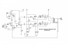
Dont know exactly what Alastair is using, but here is a link to Power Drive.
Power-drive
The scheme Im using follows nearly exactly the Power-drive scheme, except for a few cct value changes to suit the available voltage supplies I had available from my mains Tx Ive also added a zener for protection to the MOSFET S-G junction. Its voltage is 12v half watt type.--I had an earlier failure caused by gate-punch through, when I changed a pre-amp tube without shutting down.......
Im driving the power-drive section from a conventional resistor loaded phase-splitter and not the CCS loaded design part as in the original Power-Drive scheme.....
--Nice and easy to set-up the bias, just adjust the bias-pot and forget it--Its VERY stable even after many many hours use/abuse and with those new unused Chinese tubes, I got off fleabay especially to mess about with it .............
Im currently working with +150 and -50 volts for the power-drive rails, and have values of 2.5K from 811A grid to the -50 V rail and a MOSFET potential devider made up from a 20K pot with a 47K to the +150 rail and a 22K to the -50V rail and apart from the addition of the zener, Ive used the power-drive basically as-is.
Use a fair sized heat-sink for the MOSFET's or say, an old Pentium processor heatsink--Run the fan from a rectified 6v heater supply and youll have a nice cool MOSFET's and no fan-noise.--My current breadboard set-up for heatsink, holding both MOSFETS
Currently, my P-P has only the one bias-pot potential divider supplying both the MOSFET's driving the pair of 811A tubes. There is only a difference of around 3mA between the tubes idle-bias and these were not bought as matched tubes--Maybe Im just lucky here...............
Ive tried adjusting the bias point, and anything above around 30 mA sounds good, Below this and you definately start to lose something...................
Due to the fact its a source follower design there is near total transparency, you dont get any 'sand-sound' from it--It seems an ideal option to the usual cathode follower set-up to drive the 811A. Plenty of drive-current for those high transients! I would really recommend you give it a go--It really does wake up the amp!
Considering that the cathodes look so delicate and hot in comparison to the usual type indirectly heated O/P valves which Im used to, I cant believe the power these tubes will supply--I half expect them to pop at any miniute!--Ive not treated this bread-board with much respect either--Ive really caned it many times, almost trying to blow something but it just keeps going great!
jim said:Hi,
I once build the schematic in "astouffer's" (post #5).
Sounded very nice although a bit sharp at the top.
5 clean watts.
For a collection of 811a schematics :
my page
Greetz,
Jim
Jim: Any thoughts as to why the amp shown in #5 had the characteristic you describe?
For your list of zipped 811A material, do you have a personal favorite sans IT transformer?
OT, it is threads like this one that keep me coming back!
corbato said:I tried DC at filament. While it got rid of the hum completely, I am yet to find a cheap and cool method that can be eventually used in my proposed setup. I am using CT 6.3v AC and the hum is inaudible from my listening position
Why not try this. Cheap and easy: http://members.aol.com/sbench/humbal.html
Sheldon
speaker said:
Jim: Any thoughts as to why the amp shown in #5 had the characteristic you describe?
For your list of zipped 811A material, do you have a personal favorite sans IT transformer?
OT, it is threads like this one that keep me coming back!
Hi,
I built that one with a Lundahl LL1620 opt which I latter used in a 2A3 amp. The same sort of sharpness here so I think the Lundahl could be the cause.
As for the other schematics in the list, I only built the one I described above due to too much things to experiment
But I think it's easier (and cheaper) to build a 811A amp with a direct coupled driver than with an interstage.
Greetings,
Jim
So this thread keeps bouncing back
That Steve Bench idea is crying out to be implemented ASAP. I am determined not to use DC for heating. Thanks Sheldon for linking that.
I wonder how would DH tubes such as the 801 or the 307A would perform the role of the driver tube. Has any one given a thought or actually tried them out?
That Steve Bench idea is crying out to be implemented ASAP. I am determined not to use DC for heating. Thanks Sheldon for linking that.
I wonder how would DH tubes such as the 801 or the 307A would perform the role of the driver tube. Has any one given a thought or actually tried them out?
corbato said:So this thread keeps bouncing back
That Steve Bench idea is crying out to be implemented ASAP. I am determined not to use DC for heating. Thanks Sheldon for linking that.
I wonder how would DH tubes such as the 801 or the 307A would perform the role of the driver tube. Has any one given a thought or actually tried them out?
Steve's site has some of the most interesting stuff on tubes anywhere. But, it ain't organized to find some things so easily. The 801amp was actually designed as a driver. In this section, he gives the details: http://members.aol.com/sbench/testamp.html
He provides some links in this section for each element of the whole project.
I'm in the process of building his 801 as a low power amp. Just got the transformers.
Sheldon
"That Steve Bench idea is crying out to be implemented ASAP. I am determined not to use DC for heating."
I suppose it's a matter of preference. These days, DC for heaters is so easy that there's no reason not to use it. For my project, heater power is from an 8.0Vrms xfmr, solid state bridge rectifier (16A, 50V), 20000uF filter capacitor, and a FAN1084 voltage regulator (4.5A rated, 2.7A delivered). The calculated ripple rejection is some 80db calculated, and too low to measure. This gives a very quiet heater supply that removes the heater hum problem completely. The problem with AC on the heaters is that, even if you can't hear the hum, enough still remains to mix with signal frequencies to cause additional IMD products.
The main problem with SB's idea is that it uses raw, full wave, AC with additional harmonic components. There is also the possibility of additional phase shifts, resulting in incomplete cancellation. This scheme has all the ear marks of a SLAGIATT[*].
[*]Seemed Like A Good Idea At The Time
Cathode stress?
Miles--
How about that phenomenon whereby, the directly cathode itself, gradually thins at one end and thickens at the other due to the current single-direction flow,--Apparently, this causes early tube cathode failures by O/C.............
Also, the effect of unequal bias along the filament's length, will cause high emission points and low emission points along its length, and could I suppose, concievably cause cathode-stripping under certain conditions from certain areas, of the cathode filament
Suppose it would be possible to arrange a DC reversal each time the amp is powered up to reduce this problem..........
Some say, and Ive heard the difference myself, that a DC heater DHT sounds 'sterile', --somewhat losing 'feeling'/presence-whatever you like to call it..........
Most of these old directly heated valves were never designed for DC heating anyway, so I think if you are looking for absolute quality with no colouration, by intermodulation distortion caused by heater-hum however small, I would recommend you stick to standard sleeve unipotential cathdes, and leave the DHT etc in the parts bin!...........
I think that Steve Bench's idea certainly goes a long way in the reduction of hum, and hence intermodulation distortion to very low and acceptable levels, while tackling the problem of retaining the type of supply that the valve was designed to use, and probably took quite some time to evolve to its current iteration, and not some 'quick-dodge' as you seem to think............
"How about that phenomenon whereby, the directly cathode itself, gradually thins at one end and thickens at the other due to the current single-direction flow,--Apparently, this causes early tube cathode failures by O/C............."
Phenomonon or old wives' tale? I haven't found anything that verifies such a thing, nor any data that suggests that it causes premature failure. Light bulbs operate at much higher filament temps, use even more delicate filaments, and there is no suggestion that DC causes faster burnouts. Everything suggests the opposite, in fact: when operated on DC, the filament isn't subjected to vibratory stresses caused by stray magnetic effects.
"Also, the effect of unequal bias along the filament's length, will cause high emission points and low emission points along its length, and could I suppose, concievably cause cathode-stripping under certain conditions from certain areas, of the cathode filament"
That happens anyway, regardless of the use of AC or DC.
"Some say, and Ive heard the difference myself, that a DC heater DHT sounds 'sterile', --somewhat losing 'feeling'/presence-whatever you like to call it.........."
Goes to personal preference. If you like it that way, then why bother with AC hum cancellation in the first place?
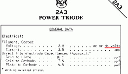
"Most of these old directly heated valves were never designed for DC heating anyway..."
Spec sheet (attached) says otherwise.
"I think that Steve Bench's idea certainly goes a long way in the reduction of hum, and hence intermodulation distortion to very low and acceptable levels..."
DC power goes even further.
"while tackling the problem of retaining the type of supply that the valve was designed to use, and probably took quite some time to evolve to its current iteration, and not some 'quick-dodge' as you seem to think............"
Yeah, I've thought about it, and I've concluded that it is a "quick dodge". (Although I had another term for that in mind.)
Phenomonon or old wives' tale? I haven't found anything that verifies such a thing, nor any data that suggests that it causes premature failure. Light bulbs operate at much higher filament temps, use even more delicate filaments, and there is no suggestion that DC causes faster burnouts. Everything suggests the opposite, in fact: when operated on DC, the filament isn't subjected to vibratory stresses caused by stray magnetic effects.
"Also, the effect of unequal bias along the filament's length, will cause high emission points and low emission points along its length, and could I suppose, concievably cause cathode-stripping under certain conditions from certain areas, of the cathode filament"
That happens anyway, regardless of the use of AC or DC.
"Some say, and Ive heard the difference myself, that a DC heater DHT sounds 'sterile', --somewhat losing 'feeling'/presence-whatever you like to call it.........."
Goes to personal preference. If you like it that way, then why bother with AC hum cancellation in the first place?
"Most of these old directly heated valves were never designed for DC heating anyway..."
Spec sheet (attached) says otherwise.
"I think that Steve Bench's idea certainly goes a long way in the reduction of hum, and hence intermodulation distortion to very low and acceptable levels..."
DC power goes even further.
"while tackling the problem of retaining the type of supply that the valve was designed to use, and probably took quite some time to evolve to its current iteration, and not some 'quick-dodge' as you seem to think............"
Yeah, I've thought about it, and I've concluded that it is a "quick dodge". (Although I had another term for that in mind.)
Attachments
Miles Prower said:[BThe main problem with SB's idea is that it uses raw, full wave, AC with additional harmonic components. There is also the possibility of additional phase shifts, resulting in incomplete cancellation. This scheme has all the ear marks of a SLAGIATT[*].
[*]Seemed Like A Good Idea At The Time [/B]
Except that he actually implemented it and got good results, both measured and subjective. But before that, he actually did a comprehensive test of the whole series of AC harmonics. Of course his subjective evaluation could be faulty, but I'm inclined to believe him. He's certainly done lots more hands on experimentation than most. Personally, I think it's rather elegant, so I'm further inclined to try. Anyway, as I said, it's cheap and easy to try. Don't like it, DC remains an option. Nothing ventured nothing gained.
If you do it as he shows, you won't have phase shift problems. Nor do I think you will have much in the way of additional harmonics. BTW he measured hum IMD at around 0.14%, up until clipping, for the residual hum due to transconductance changes with filament temperature.
Sheldon
Im with you on this, Sheldon,
'Follow the croud, Do the Quick-Dodge and do DC..............'
Im sure that Steve Bench has better things to do, than to try and find an alternative to DC UNLESS there is a dang good reason to do so.........
Just because SOME data sheets specify both AC/DC heater operation, doesnt mean they all do--The USUAL supply was nearly always AC unless you are thinking of accumulators and battery radios..............
As they say, "Dont knock it, Till you try it..........."
Miles Prower said:"How about that phenomenon whereby, the directly cathode itself, gradually thins at one end and thickens at the other due to the current single-direction flow,--Apparently, this causes early tube cathode failures by O/C............."
Phenomonon or old wives' tale? I haven't found anything that verifies such a thing, nor any data that suggests that it causes premature failure. Light bulbs operate at much higher filament temps, use even more delicate filaments, and there is no suggestion that DC causes faster burnouts. Everything suggests the opposite, in fact: when operated on DC, the filament isn't subjected to vibratory stresses caused by stray magnetic effects.
I think you are missing the point here, light bulb filaments are not required to emit electrons. What this wives tale is about is a sort of 'cathode stripping' effect, due to a different cathode current being supplied from different portions of the filament cathode. This would be a serious problem in something like a high gm DHT, since the filament voltage drop would be quite considerable in comparison with the required bias voltage, creating seriously different emission requirements along the filament. Even then, in order for it to be a problem, Ik would have to be high. In reality, I am not sure there is such a DHT tube in audio use, or indeed, I am not sure it even exists. From what I have seen, with 5V filaments and bias voltages on the order of -50V, there is a 10% variance, which i doubt would create a problem unless the tube was simultaneously used outside maximum specs.
Guys, I'm not opposed to DC on filaments. I have no experience in that regard either way. That said, some people have reported a subjective loss in sound quality with DC. And there have been extensive discussions on this forum on the best sounding ways to implement DC. And Tent labs sells a DC heater supply with the claim that high impedence is key to good sound. Again, no personal experience here, and, as Miles said, maybe it just boils down to personal preference. But all this suggests that maybe things are not so cut and dried.
Miles, the only thing I take issue with in your comments is dismissing Steve's approach as half-baked. A thorough read of his site makes clear that he takes a careful scientific approach to explore areas that intrigue him - areas that are often outside the usual and therefore sometimes pretty enlightening. I like his creative but scientific explorations. And when an experimental circuit doesn't sound that great he says so too. As far as I've seen in my limited experience, he's one of the more innovative Diyers that is willing to share openly. That doesn't make his suggestions immune to criticism, but I think the AC hum cancellation approach at least deserves consideration as a real option. It was not my intent to imply more than that.
Sheldon
First of all, I use DC on the filaments in most of my DHT amps. It is the simplest, most effective way to kill the hum. The effect of the voltage gradient along the filament wire must be considered. For most of the common audio tubes it is indeed less than 10% of the bias and can probably be ignored.
This thread was however about the 811A, and the effect can not be ignored with this tube. At the voltages that I use anyway (600 to 1000 volts) 6.3 volts can be the difference between cutoff, and 30 mA of plate current. This can cause lifetime problems with the tube. The effects of DC filament voltage can be heard, even with my bad hearing. I like others can't totally eliminate the hum when using AC and the usual hum balance pot, even with my 86db speakers.
I have not tried the Steve Bench approach, but the guy does have good science. I have taken a different route, AC heating using 50 KHz filament current. I did some experimenting with this about a year ago and I can tell you that the filament power must be a clean sine wave if this is going to work. Otherwise you will get all sorts of intermodulation products that cloud up the FFT scope, and the sound.
- Status
- This old topic is closed. If you want to reopen this topic, contact a moderator using the "Report Post" button.
- Home
- Amplifiers
- Tubes / Valves
- 811-A amp