> 100 Ohm change in load will cause abrupt changes in the distortion figures.
SPICE is sometimes pretty close, and sometimes it goes way off-track. NEVER believe it without question. We know a real tube will not show major change of performance for minor change of condition. Your posted numbers look "possible", so the way-out numbers are probably some type of mathematical collision. But even so, I would not put much weight on 0.05% versus 0.2%: both calculations may be wrong, even assuming the real tube matches the model (it never does).
You have, however, fallen into one SPICE-trap. In SPICE, parts are free. It is too easy to throw lots of big parts on the plan and get great numbers. As others have hinted, a few of those squiggles are BIG HEAVY COSTLY parts. That may be OK if you have the cash and space and floor-support. But you should also ask if you could apply that same money differently and get a better result.
Bad Example: the gross spec, >10W <1% THD, could be met with push-pull 6V6, overall feedback, much smaller audio iron, much-much smaller power transformer and filtering. Yes, I know you are not looking for yet another mini-Dynaco or small-Fisher, you want your wide-open SE triodes.
But here is another idea: today, caps are cheaper than chokes, and a big-C filter is usually your best buy. However caps are "cheap" only up to 450V, after that you must de-rate and series-string or buy huge oil caps. Also tubes up to 500+V can use efficient oxide-coated cathodes, over 1,000V secondary emission beats the oxide to death and we must use less efficient solid cathodes. Emission current is limited by low heater-cathode efficiency, so the way to big power is high voltage. Thorium in tungsten cathodes favor running the plate up in the 1,500-2,500V range. (The 211's plate rating, 1,250V, seems low, especially considering that at zero-bias it is almost dead up to several hundred volts.)
Also: I gather you never built a tube amp this big. 1,000V is NASTY DANGEROUS stuff. I took 600V through a finger once and it is still numb, 30 years later. 250V is also potentially fatal, but 600V or 1,000V really increases the odds of serious bodily harm.
I really think you should start at less-insane voltages.
10W SET.... well, four 2A3 or a couple.three 300Bs will do that at "only" 350V-400V supply. You self-bias it, not so much for stability but because the low-Mu 2A3 needs big grid drive (~60V) and your driver will need about 5 times the grid-bias to do the job well. Now your driver and output can eat the same power rail, eliminating quite a lot of parts. Your really low impedance 417 can easily drive four self-bias 2A3 grids and their gridleak resistor. The low load impedance, a few Kohms, makes output transformer winding very simple (winding capacitance hardly matters).
One objection is that 2A3 and 300 went from well-used to old-junk and bounced: are now cult-status, with high prices. (I remember when you could get baskets of 2A3 for $0.33 each, now $100-$500+).
Some bottleheads will sneer, but triode-strapped 6550 makes a respectable output device. No, it isn't a true triode, though I'm not sure the electrons can tell the difference. (Triode-strapped 807 was good enough for Williamson.) No, it isn't directly heated, a concept that went very far out of fashion before it became the "IN" thing again. A couple 6550 triodes will make a heck of a sound in any efficient speaker. Maybe not >10 Watts, but not many dB less. (BTW, I have not seen a SPICE model for a pentode, even triode-strapped, that seemed as accurate as eyeballing charts.) Being a cheapskate, I would think about 6SL7 to drive it: plenty of voltage-gain for CD source and 250K grid-loads.
I am no longer the heavy-feedback fan I used to be, but one thing feedback IS good for is turning low hum into very low hum. The compact affordable hi-fis of the 1950s would not have been possible without NFB. (But in retrospect, maybe they were TOO compact and affordable....)
Re: Elevated 417 filament
PSE 211 with a 1kV+ PS with four big, heavy filter chokes for a measly 16 watts or so is a little extreme. You might be better off with a cheaper, lower µ valve like a GM70 or something if you must have a transmitter valve SE amp. The lower µ valves allow you to swing closer to 0Va before drawing g1 current at the expense of more severe driving requirements. Even better, if you can find a high-ish µ and high-ish gm valve which tickles your fancy, you can have both!
The idea is that there is a parasitic thermionic diode between the heater and cathode which is turned "on" while the heater is negative with respect to the cathode (after all, the heater is just a bit of hot wire). Elevating the heater to a higher potential is done to reverse bias this parasitic diode and hopefully reduce any hum which is induced by it.
PSE 211 with a 1kV+ PS with four big, heavy filter chokes for a measly 16 watts or so is a little extreme. You might be better off with a cheaper, lower µ valve like a GM70 or something if you must have a transmitter valve SE amp. The lower µ valves allow you to swing closer to 0Va before drawing g1 current at the expense of more severe driving requirements. Even better, if you can find a high-ish µ and high-ish gm valve which tickles your fancy, you can have both!
Radames said:Tim, could you explain me how elevating the filament supply will reduce hum?
The idea is that there is a parasitic thermionic diode between the heater and cathode which is turned "on" while the heater is negative with respect to the cathode (after all, the heater is just a bit of hot wire). Elevating the heater to a higher potential is done to reverse bias this parasitic diode and hopefully reduce any hum which is induced by it.
Re: PSU hum
Lemme see here...
Oh, don't forget that hum in the driver will cancel hum in the output, just how much depends on relative loading, filtration, gain and so forth.
So anyways, 750VAC rectified is naturally 750Vrms, but most of that is 675VDC DC output (choke input filter, since C10 isn't enough except at low current). I don't know what ripple RMS looks like. Let's arbitrarily say it's 400V ripple at the rectifier. This hits the first choke and cap as a voltage divider, 10H to 51uF, reactance (120Hz) 7540 ohms choke, 26 ohms cap, for a ratio (I/O) of 0.0034, or 1.38V. Neglecting the second filter stage, this would appear as 0.78 *1.38 = 1.08V on the transformer. At 8 ohms output (you left it unmarked, so I'm making an assumption), this is 36.5mV ripple at the speaker. Full power of 15W or so into 8 ohms is 11V, for a noise floor of 304 times under full power output, or -24.8dB (-49.7dBV).
Not too great, could be worse, could be better. As mentioned, some amount of cancellation will occur (this can be calculated).
But choke input is insufficient voltage, something you seem to have overlooked; so pulling the first choke, leaving 51uF at the rectifier, 10H in series, and the other 51uF, will net probably 1.4 x Vrms = 1050V or so (may be lower depending on current draw; 51uF isn't much, I'd go for 100uF). Ripple is maybe 8Vrms, and well since it's the same filter as above, you can see already that hum is 8/400ths lower, sounds SFA to me!
Tim
Radames said:Hey Tim thanks for the reply.
I calculated that every LC stage of the PSUs will give me around 58dB of hum attenuation. So together would give more than 100, and that's what I wanted to get.
Using a single LC could let the hum be heard through the speakers if my calculations are correct. But may be that's all math rubble.
Lemme see here...
Oh, don't forget that hum in the driver will cancel hum in the output, just how much depends on relative loading, filtration, gain and so forth.
So anyways, 750VAC rectified is naturally 750Vrms, but most of that is 675VDC DC output (choke input filter, since C10 isn't enough except at low current). I don't know what ripple RMS looks like. Let's arbitrarily say it's 400V ripple at the rectifier. This hits the first choke and cap as a voltage divider, 10H to 51uF, reactance (120Hz) 7540 ohms choke, 26 ohms cap, for a ratio (I/O) of 0.0034, or 1.38V. Neglecting the second filter stage, this would appear as 0.78 *1.38 = 1.08V on the transformer. At 8 ohms output (you left it unmarked, so I'm making an assumption), this is 36.5mV ripple at the speaker. Full power of 15W or so into 8 ohms is 11V, for a noise floor of 304 times under full power output, or -24.8dB (-49.7dBV).
Not too great, could be worse, could be better. As mentioned, some amount of cancellation will occur (this can be calculated).
But choke input is insufficient voltage, something you seem to have overlooked; so pulling the first choke, leaving 51uF at the rectifier, 10H in series, and the other 51uF, will net probably 1.4 x Vrms = 1050V or so (may be lower depending on current draw; 51uF isn't much, I'd go for 100uF). Ripple is maybe 8Vrms, and well since it's the same filter as above, you can see already that hum is 8/400ths lower, sounds SFA to me!
Tim
Oh, and I was going to comment on a regulator:
Okay, so it can kill hum. So can't a simple linear power supply. It may be lighter, but not much lighter than a conservatively designed supply (audiophoolery does not apply to my posts). And, of course.... you have to ask yourself... are you feelin lucky? (No wait)... you have to ask yourself, do you want to waste all that voltage? An LC filtered supply wastes *no* DC voltage.
Tim
Regulator option/ PSU issues
Hey! This is awesome! Thank you all!
Ok, Sy convinced me yesterday to look up the 317 options and there I went with my HP calculator. After trying to understand Morgan Jones' regulators for a while (he makes it quite hard), I figured that I still need one LC and then the regulator. I would save 1 LC combo and >40lb!
The price of the whole thing, however, rises. As PRR well mentioned caps that can take more than 450V get expensive and the regulator option implies adding 2 more caps than in addition to the ones I have already. Weight is still an important improement yes.
The choice of the caps an 193Qs was governed by whatever I could fetch from the Partsconnexion site with enough rating to handle the voltage and current (234mA at the operating point and 1006VDC). The 193Q is rated 500mA 1000VDC, the lower model is rated 300mA but only 800VDC. But may be this does not matter much because there is no potential difference (or very little; set by the resistance of the choke) between the choke terminals... If that is correct I could use the 193P at half the weight and 15 bucks less.
The choice of caps was again to find stuff that would take more than 1006V across it. The only one I could find (at PC) that could take >1006V was that 51uF Solen.
I admitt, the PSU has many problems, mainly weight and cost.
Cheers!
Rada
P-P vs SE and valve choice and modelling
PRR very well pointed that a P-P is a better alternative. Morgan Jones could not agree more and he convinced me in his book.
I am a true beginner and I chose SE due to the simplicity of the circuit topology and ease of the calculations. I actually could not quite figure the inner workings of the P-P topology. I admit I need to study it more and re-read Morgan Jones' book.
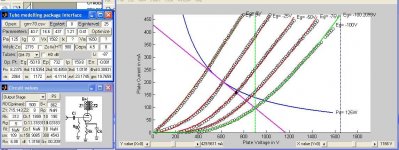
PRR, I don't use any SPICE (only in my food). I actually don't know how to use any SPICE software. I used SwitcherCAD just to draw the circuit because it seemed faster than doing it in Photoshop.
All my calculations and loadline choosing is done partly in an old fashioned way. Drawing a million loadlines, calculating all the tube parameters and the values of the elements on the circuit for each line. I choose the line looking at the THD figures, power and coupling elements to ensure good bandwidth.
Of course I don't do it with a pencil, I have a Matlab program that does all the calculations for me (I am good with Matlab, bad with pencils). The tube models are based on Norman Koren's equation. So far I have implemented only the triode model, and that's why there is no pentode in my design . I know, it is a stupid reason...")
If anyone uses Matlab and is interested in having a look at my program, just e-mail me.
I looked at different tubes: 845, 2A3, 300B, 211, 45, 801A, 6C33C-B and 27 as output tubes. Due to either price or power output I ended only with the 845 and 211. The 211 won because I found I needed less voltage to get the same power, and the linearity was superior to that of the 6C33-CB. The 2A3 and 300B are very expensive.
For input tubes, the only ones I could find that allowed to maintain the 2 stage topology were the 417A and the 6C45-PE. The linearity of latter is rather poor though.
Cheers,
PRR very well pointed that a P-P is a better alternative. Morgan Jones could not agree more and he convinced me in his book.
I am a true beginner and I chose SE due to the simplicity of the circuit topology and ease of the calculations. I actually could not quite figure the inner workings of the P-P topology. I admit I need to study it more and re-read Morgan Jones' book.
PRR, I don't use any SPICE (only in my food). I actually don't know how to use any SPICE software. I used SwitcherCAD just to draw the circuit because it seemed faster than doing it in Photoshop.
All my calculations and loadline choosing is done partly in an old fashioned way. Drawing a million loadlines, calculating all the tube parameters and the values of the elements on the circuit for each line. I choose the line looking at the THD figures, power and coupling elements to ensure good bandwidth.
Of course I don't do it with a pencil, I have a Matlab program that does all the calculations for me (I am good with Matlab, bad with pencils). The tube models are based on Norman Koren's equation. So far I have implemented only the triode model, and that's why there is no pentode in my design . I know, it is a stupid reason...
If anyone uses Matlab and is interested in having a look at my program, just e-mail me.
I looked at different tubes: 845, 2A3, 300B, 211, 45, 801A, 6C33C-B and 27 as output tubes. Due to either price or power output I ended only with the 845 and 211. The 211 won because I found I needed less voltage to get the same power, and the linearity was superior to that of the 6C33-CB. The 2A3 and 300B are very expensive.
For input tubes, the only ones I could find that allowed to maintain the 2 stage topology were the 417A and the 6C45-PE. The linearity of latter is rather poor though.
Cheers,
PRR: Sane advice. That's really the best way to go for 99.99% of the builders.
Radames, did you read through Maida's app note? It's pretty straightforward. The main thing is to not be afraid to use lots of protective diodes and understand that silicon things pop when you fiddle around with them carelessly. I've got a prototype running here at 700V using an NTE165 as the pass device; it worked fine with a MOSFET there, too, a 2N6770. I admit that I blew up a few devices during troubleshooting...
Radames, did you read through Maida's app note? It's pretty straightforward. The main thing is to not be afraid to use lots of protective diodes and understand that silicon things pop when you fiddle around with them carelessly. I've got a prototype running here at 700V using an NTE165 as the pass device; it worked fine with a MOSFET there, too, a 2N6770. I admit that I blew up a few devices during troubleshooting...
Re: P-P vs SE and valve choice and modelling
PP is not hard - go have another look at the book. It is nothing more than two SE stages working in opposing phase.
You consider this poor linearity?

PP is not hard - go have another look at the book. It is nothing more than two SE stages working in opposing phase.
Radames said:For input tubes, the only ones I could find that allowed to maintain the 2 stage topology were the 417A and the 6C45-PE. The linearity of latter is rather poor though.
You consider this poor linearity?
GM-70, chokes and safety
Jason, thanks for the suggestion. I have just downloaded the GM-70 datasheet and Vp vs Ip plot from the net. I will try to implement a model and look at it.
I will also look at using an cap input as Shchematic suggested. That seems to make sense.
PRR: Thanks for the safety advice. I am also aware that working with much lower voltages the 300mA or so out of any of those supplies will put my heart (and pacemaker if I had one) to retirement. I am an electrophysiologist and at the work at the lab with electric equipment (some running at a few KV >10A) so safety is a daily concern at my workplace. Point well taken (cannot be stressed hard enough).
6C45-PE
Jason,
You are totally right! I was talking out of my ... yes I was!
I just opened my Matlab modelling stuff and reworked the 6C45-PE.
The reason I didn't finally chose it is because to get 3V peak-to-peak of grid swing and 100V peak-to-peak plate swing, I had to lower the resistance of the load so heavily that the distortion figures were not very nice (the loadline goes into the bottom part of the Vp vs Ip curves.
I think that less than 3V peak-to-peak in at the input is too little. This tube, however, could make a great driver for the 845!
Cheers,
Rada.
PS: Oh! Putting the chokes on the ground side is somethin I will definitively look at. That will shave 27 ponds!!! (and 30 bucks) allowing me to use the 193P instead of the 193Q chokes. However, giving the figures posted by Sch3matiC I could possibly get by using a single choke.
GM-70
Hi Jason,
I looked a bit to the GM-70 tube. From the datasheet I have, it looks like under the 125W line there is quite a bit of non-linearity. May be I am messing up something, but it looks to me like a poor choice for an output stage.
Letting the grid swing some 100V the THD figures are not very encouraging. With 50 V grid swing the things get quite better, a very steep loadline can be used and therefore a simpler OPT, but the power drops quite a bit.
I don't know... it doesn't seem linear enough.
Attachments
This is the datasheet that I've seen.
http://www.conusaudio.com/Specs/GM70.pdf
The sockets for the GM70 are rather hard to come by, so perhaps a triode-strapped 813 may be more appropriate:

(in 10V graduations from 0V)
Radames, there is no need to reduce the load on the driver valve to reduce gain - having a 3V input sensitivity just necessitates an active preamp to allow the amp to reach full output, and increases distortion due to reduced load impedance. A triode generally is happiest where its load impedance is around >50ra. An inductively loaded driver may be in order if very large voltage swings are required becuase it allows the anode to swing above the power supply voltage.
These transmitter types tend to have rather low maximum grid circuit resistance requirements because they often will draw grid current. I believe the 813's is in the order of 20KW or so.
http://www.conusaudio.com/Specs/GM70.pdf
The sockets for the GM70 are rather hard to come by, so perhaps a triode-strapped 813 may be more appropriate:
(in 10V graduations from 0V)
Radames, there is no need to reduce the load on the driver valve to reduce gain - having a 3V input sensitivity just necessitates an active preamp to allow the amp to reach full output, and increases distortion due to reduced load impedance. A triode generally is happiest where its load impedance is around >50ra. An inductively loaded driver may be in order if very large voltage swings are required becuase it allows the anode to swing above the power supply voltage.
These transmitter types tend to have rather low maximum grid circuit resistance requirements because they often will draw grid current. I believe the 813's is in the order of 20KW or so.
Re: GM-70
What's Vmax? 1.65kV I think I see? Crank that beotch!
Drop RL. Definetly. It's almost = Rp on your graph...
Or if you don't want to muck with HV (a wise decision), hook up a cathode follower and give that grid some positive voltage excitement. (You'll need global NFB because RL will be lower than Rp - bad damping factor - class A2 is sort of like UL to pentodes in that regard.)
Tim
Radames said:I looked a bit to the GM-70 tube. From the datasheet I have, it looks like under the 125W line there is quite a bit of non-linearity. May be I am messing up something, but it looks to me like a poor choice for an output stage.
What's Vmax? 1.65kV I think I see? Crank that beotch!
Drop RL. Definetly. It's almost = Rp on your graph...
Or if you don't want to muck with HV (a wise decision), hook up a cathode follower and give that grid some positive voltage excitement. (You'll need global NFB because RL will be lower than Rp - bad damping factor - class A2 is sort of like UL to pentodes in that regard.)
Tim
Thanks to all
Ok, this post has been of extreme value for me. I actually did not expect such an incredible response.
Thank you all guys, you got me thinking again about the circuit, especially the problems with the power supply. In addition, a 6C45-PE project may be spawning out of this thread.
Thanks again.
Sincerely,
Radames
> The 2A3 and 300B are very expensive.
You can find new copies for $50-$100. They were made by semi-forced labor instead of the contented RCA gals or the very skilled WE folks, and may not stand the abuse of the originals, but good to learn on. And considering the cost of over-400V power, not necessarily more expensive for a complete amp.
> I don't use any SPICE .... All my calculations and loadline choosing is done partly in an old fashioned way. Drawing a million loadlines, calculating all the tube parameters and the values of the elements on the circuit for each line. I choose the line looking at the THD figures, power and coupling elements to ensure good bandwidth. Of course I don't do it with a pencil, I have a Matlab program that does all the calculations...
Hmmmm... Matlab is old fashioned?
Whatever. SPICE is an old-old-old FORTRAN (now C?) program to chew on electronic circuits and spit out "answers". I think your Matlab tool must be a partial re-invention of that wheel.
I just glanced at your screen-clip. If you can bundle that stand-alone (i.e. don't have to buy Matlab) you can sell it. I like the interface better than a commercial product I own.
Old-fashioned and STILL useful is the "5% distortion rule".
First: while M-J is a great guy, I think you would benefit from reading Radiotron Designer's Handbook (3rd) and then Radiotron Designer's Manual (4th). The 3rd is small and usually black and can be bought for $15 reader-copy. The 4th is red, a real lap-full, and runs $50+ used or on CD-ROM. Though you can find scans on the Web, holding the actual book is holding a hunk of history.
Over half of Radiotron is useful to audio geeks (it is of course a lot about radio) but a quick skim would be chapters 12, 13, 14, and 15. See Chap 13 page 550 (pdf 7) for "5% distortion rule".
By the way: do NOT fear 5% or even 10% THD in a single-ended no-feedback amp. It is mostly 2nd harmonic and nearly inaudible, quite unlike the 7th and 13th and other strange squeaks that come out of high-feedback amps and must be held to the point-oh level.
And don't get stuck on a specific power specification. Some jobs need specific power, but home audio doesn't. I've been very happy in my office with a 6550 making 0.8 Watts; I've been thrown out of a dorm for a 25 watt. And few-Watt amps are FAR easier to build than many-Watt amps. The real trick is to find happy combinations of available low-price parts, and accept what you get. Power is way down the list of attributes to maximize.
> I chose SE due to the simplicity of the circuit topology and ease of the calculations. I actually could not quite figure the inner workings of the P-P topology.
Two SE working together. In simple parallel, power doubles, THD is unchanged.
But if you flip signal phase into one tube (and un-flip it at the output), some wonderful things happen.
Even-order curvature nearly cancels. That makes THD computation harder, but in almost any case you can assume that THD will be in the 2% range, not the 10% range that SE makes when pushed near its limits. (However 3rd has a different sound than 2nd.)
With SE and low Rp or high V+, lower load impedance means more power but more distortion. Push-pull cancels that type of distortion so well that you can reduce the per-tube load and get more power while still a reasonable distortion number. Compared to one tube, two in push-pull make 2, 3 even 4 times the power of one tube.
Transformer DC cancels. That DC current in a SE stage is equivalent to a full-power infinitely low bass tone soaking the iron with magnetic flux. That forces all kinds of compromises, but size/weight/cost is always much better with push-pull than SE.
> I am an electrophysiologist and at the work at the lab with electric equipment (some running at a few KV >10A) so safety is a daily concern at my workplace.
So you know. And I hope nobody here ever needs a cardiac electrophysiologist. But even so, your work gear has been designed for safety, tested and approved, and you have been trained. In DIY, there is no FDA or OSHA or workplace safety officer looking over your shoulder.
> max grid resistor for the 211?
The only sane way to drive beasts like this is transformer-coupled. The designers makers didn't bother to test negative-bias grid current because it would always be drawn-off by a low-resistance winding. You are on your own here. 22K may be safe, but sure is an impressive amount of drive power.
> to get 3V peak-to-peak of grid swing and 100V peak-to-peak plate swing, I had to lower the resistance of the load
No! "Low loads are BAD!!" Jason says 50*Ra which may be a typo: 2*Rp gives best power, 10*Rp gives lower distortion at significant drop of power, 5*Ra gives a nice compromise unless you are really hurting for power. And if you are so short of power, fudging the load isn't going to make you jump for joy. You gotta raise voltage and current. Even if that means getting a bigger tube (or re-considering the power spec).
Matlab etc
Hey PRR,
I am checking the Radiotron Manual right now. I will definitively read through.
Other valves an lower the power are becoming more present in my mind after all the comments about my PSU. It obviously needs more work and lowering the voltage would make stuff easier and cheaper. I am thinking in applying all those savings to other tubes to maintain the cost of the amp.
About my matlab wheel, it is an excercise to learn how the tubes work and how the components of the stage interacts. I am on the way of adding other stage topologies and pentode modelling. I do not learn much by learning to use software. By programing the software I learn much more than programming
Doing a stand-alone is quite some work (need to re-write the code and pack it). I may do it while on vacation. If it happens it will get around for free, I will not sell software.
I you or others have Matlab and want to try, just drop me a line (verdee@cshl.org). I also found that using Engauge digitizer is great to digitize all the tube cuves from the PDF or GIF datasheets and obtain X-Y coordinates to plug on the model. I have values for many triodes in .csv files, if someone is interested.
Best,
Radames
- Status
- This old topic is closed. If you want to reopen this topic, contact a moderator using the "Report Post" button.
- Home
- Amplifiers
- Tubes / Valves
- My first design. PSE 211 to review.