Hello,
I'm faffing around again working out which project I want to do! I think I have about 6 or 7 on the go at the moment Anyway, I've been working on this since the weekend, I have a DIY hifisupply Ella that I built around a year ago and I fancy rebuilding it now (specially as theers a new p2p one out now! gotta keep up!) and improving it a bit. I've been running in triode mode with no feedback for the last few weeks and I like it, so I thought I might make it more permanent and do a few other things while I'm at it. Current plans are move the 6SN7's to the front, between their respective output tubes. Input transformers also at the front, and RCA's. Tube rectifiers where the 6SN7 used to go, and chokes right at the back where the 6922 used to go. Hopefully this will mean something to those of you familiar with this amp.
Anyway, here's the schematic I've drawn up of my plans so far...any criticism, improvements tips and/or opinions greatly accepted and appreciated!
Cheers,
Steve
I'm faffing around again working out which project I want to do! I think I have about 6 or 7 on the go at the moment
Anyway, I've been working on this since the weekend, I have a DIY hifisupply Ella that I built around a year ago and I fancy rebuilding it now (specially as theers a new p2p one out now! gotta keep up!) and improving it a bit. I've been running in triode mode with no feedback for the last few weeks and I like it, so I thought I might make it more permanent and do a few other things while I'm at it. Current plans are move the 6SN7's to the front, between their respective output tubes. Input transformers also at the front, and RCA's. Tube rectifiers where the 6SN7 used to go, and chokes right at the back where the 6922 used to go. Hopefully this will mean something to those of you familiar with this amp.Anyway, here's the schematic I've drawn up of my plans so far...any criticism, improvements tips and/or opinions greatly accepted and appreciated!
Cheers,
Steve
Attachments
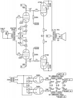
Ick, input transformer... hope it's good to 20kHz with no phase shifts.
Good and balanced...
LEDs are a bit of a waste and will let the 6SN7s drift more...
(For that matter you could fixed bias them too and get the same effect, since you've already got the negative supply for the output...)
What was the point of a) dual rectifiers, and b) hybrid rectifiers?
I can understand using two tubes if a single 5AR4 can't handle the supply current, but as long as you've got silicon in there you might as well save the wasted power and use silicon all around.
Otherwise the power supply is okay... might use a lil more filter capacitance (100-200uF) for the middle filter if you have some chunky caps on hand...*shrug*
Tim
seems like it would work fine as-is, but I would make a few changes. I would bypass the LEDs on the cathodes of the 6SN7's with some capacitors to reduce any possible voltage noise from them, and to ensure a low impedance to ground for signal frequencies. I would also increase the middle filter capacitor if possible (that feeds the output tubes). I also like to bypass my filter capacitors with a small film capacitor (I usually use some "orange drops" from old monitors and TVs) from .1(no point on the very first filter stage after the rectifiers) to a few uFs. I don't think the 33 ohm resistor in series with the GZ34 cathode is really necessary. I would have used complete SS rectification here if I started from a new design, but you might as well leave the tube rectifiers installed if you are already set up to use them. I would worry slightly about output impedance due to the lack of NFB, but wouldn't worry too much. you DO NOT want a global NFB loop around two transformers. Do you have any extra taps or windings on the OPT? I am a huge fan of using a Cathode Feedback connected output stage. You might be able to play with any extra winding or tapping to be able to use cathode feedback or perhaps take a balanced negative feedback signal and apply it to the 6SN7's. Only a little should be sufficient. But if that is not possible, the triode connected KT88's should be able to have a good enough Zout.
FWIW, the voltage noise across LEDs is insignificant at multi-volt levels (at 1mV/div on my scope, I can't see anything, so any noise at the drive level required for full output on a KT88 would be more than 90 dB down). A bypass won't hurt anything until it fails, but it has essentially no function in this circuit. I had worried that the nonlinearity in LED impedance might cause distortion in a non-CCS stage, but a few measurements put those fears to rest.
Selecting LEDs is important; some red LEDs have very low impedance (5 ohms or so) but some are much higher (like 25-30 ohms). Fortunately, mistakes are cheap.
Since the two cathodes are at AC ground (or nearly so), you only need one LED string for both tubes. This carries three advantages: lower parts count, more current through the LEDs (drops source impedance), and any noise/distortion is common mode and will be knocked down by the p-p action of the phase splitter.
I suppose the 5AR4s are used for a gradual turn-on?
The only suggestion I have is maybe try the opposite method of biasing the 6SN7s - instead of voltage sources (LEDs), try biasing them with a current source and make them a differential/long tailed pair. It will let you get rid of the input transformer, too.
The only suggestion I have is maybe try the opposite method of biasing the 6SN7s - instead of voltage sources (LEDs), try biasing them with a current source and make them a differential/long tailed pair. It will let you get rid of the input transformer, too.
I'm not too familiar with LEDs as a cathode bias source, but I was a bit worried about any possible nonliarities or impedance. Most of my LED experience has been with inicator lamps and diode/LED clippers in guitar distortion boxes.
The idea about combining hte two LED strings never hit me, but combining them will give you a very rudimentary differential amplifier. make sure not to exceed the LED's maximum current.
Please tell us how the amplifier sounds, and perhaps how it compares to other PP KT88 amps. It's quite refreshing to see something other than the usual Williamson clone or 300B amps.
SY said:Since the two cathodes are at AC ground (or nearly so), you only need one LED string for both tubes. This carries three advantages: lower parts count, more current through the LEDs (drops source impedance), and any noise/distortion is common mode and will be knocked down by the p-p action of the phase splitter.
That's a very slick trick. Is it also correct to say that since in a perfectly balanced differential pair the current through the 'tail' is constant for varying AC inputs that this connection a) reduces the AC current through the LEDs and hence the effect of impedance non-linearities and b) the remaining impact of those non-linearities is further reduced by the same common-mode rejection?
Well, constant current means just that- it's constant at DC and AC. There is a variation of voltage across the source, though- half the input votage. Having a CCS and well-matched plate resistors will automatically make the balance near-perfect, assuming an identical load on each side.
edit: Half the input voltage is only true when one side of the diff amp is grounded as in a phase splitter.
edit: Half the input voltage is only true when one side of the diff amp is grounded as in a phase splitter.
Morning, cheers everyone!!
Didn't think about the ability to share LED's. I was worried about them only passing 5mA, but that brings it up to 10mA through them which is a bit nicer as far as their linearity goes, I think. Ill have to check some datasheets again.
Yes the tube rects are there for slow turn on, and I have some hanging around, and some holes in the chassis that will look lonely without. I would like to go fully tube rectified but have no center tap. How about using 4 EZ81's in full bridge or something maybe? The tube as well as taking a while to start to turn on also takes a few seconds to turn on once it starts (if that makes any sense...) which hopefully will stop the voltage overshoot caused by the chokes at startup, specially as the caps are 400v and run quite close to that as it is.
The center cap value is limited to 75uF as these are the biggest reasonably sized film caps I can find (Wilmslow Audio). On a bit of a mission to get electrolytics out if I can. I could always parallel them, but I've only got so much space in the ready made chassis... The KT88 supply ripple is around 170mVp-p and for the 6SN7's is about 2.3mV (according to PSU designer), but hopefully this will be fine as its a push-pull??
Here's the datasheet for the input transformer:
Sowter 8920
hopefully itll be OK?
Cheers again all!
Steve
Didn't think about the ability to share LED's. I was worried about them only passing 5mA, but that brings it up to 10mA through them which is a bit nicer as far as their linearity goes, I think. Ill have to check some datasheets again.
Yes the tube rects are there for slow turn on, and I have some hanging around, and some holes in the chassis that will look lonely without. I would like to go fully tube rectified but have no center tap. How about using 4 EZ81's in full bridge or something maybe? The tube as well as taking a while to start to turn on also takes a few seconds to turn on once it starts (if that makes any sense...) which hopefully will stop the voltage overshoot caused by the chokes at startup, specially as the caps are 400v and run quite close to that as it is.
The center cap value is limited to 75uF as these are the biggest reasonably sized film caps I can find (Wilmslow Audio). On a bit of a mission to get electrolytics out if I can. I could always parallel them, but I've only got so much space in the ready made chassis... The KT88 supply ripple is around 170mVp-p and for the 6SN7's is about 2.3mV (according to PSU designer), but hopefully this will be fine as its a push-pull??
Here's the datasheet for the input transformer:
Sowter 8920
hopefully itll be OK?
Well the amp as it is I think is a Williamson clone, and my housemout may be building a SE300B soon, so I should have some decent comparisons to make hopefully. Just gotta finish my horns now!Please tell us how the amplifier sounds, and perhaps how it compares to other PP KT88 amps. It's quite refreshing to see something other than the usual Williamson clone or 300B amps
Cheers again all!
Steve
Steve, since your plan is basically to use triode strapped KT88 in P-P, did you by any chance look at these ? Just wanted to know what you (and others) thought about them ?
http://www.audiodesignguide.com/my/pp3.html
http://www.pbase.com/frankie168/image/27333147
Later than sooner (i.e. when I get bored with my Eico HF-14) I might find myself going down the same route and these are what I have found so far for a triode strapped P-P KT88 output stage.
Anybody have any thoughts on these designs ?
P.S- did I see a triode strapped kt88 p-p on diyparadiso ?
Sharing LED is good idea. Besides lower linearities, it also reduces temperature effects, and improves balance.
If LED you're using can't handle 10mA (lot's of LED can handle 10mA), why not use some power diodes?
Wow, all film capacitors for power filters? This is an expensive design.
BTW, what's your bias point for KT88? Since your cathode resistor is only 1ohm, I assume the bias point is very close to Class B. have you tried to move the point to class A as much as possible? if yes, is there any sonic improvement? (I am curious to know)
That's a fixed bias output stage: there is negative grid bias from that 220k resistors (btw the guy missed the bias supply in the schematics). I would think that the design is very towards class A... just because KT88s have so high Pa that running it in class A would result in an acceptable output power...
those 1ohm resistors are there just to check total cathode current: basic ohm's law... And no, with cathode bias and 1ohm cathode resistor that's not class B (tubes at cutoff or the like): it's just two saturated tubes that would have big THD... see that the grid will have the same DC potential of the cathode. That is saturation!
Hope this helps
Hello,
Back from work now so I can play around with ideas for this again
Percy - cheers for them, the first one is a solution I haven't seen used too much, I'll have to check it out
crtubes - finding LED's that handle 10mA isn't a problem, but I would like to find one that has low 'resistance' in the 5-15mA range if I can (i.e. not much change in voltage drop accross the LED for a given change in current). As far as caps, even the 75uF one is about £14 so it shouldn't break the bank too much... I'm it would be possible to spend more on 'lytics. Bias point will be around 350V at 100mA per tubeish, I'll have to see how hot things get when it's running, but yes it's a long way into class A. As the amp stands now I can tell the difference sonically between 40mA and 75mA
Giaime - Yep, Ill still keep the adjusting pots easily accessible though in case I need a few more beans once in a while. Any thoughts on how well a regulated bias supply would work, specially as far as stability wrt mains level and things goes. Maybe the output impedance of the supply effects things?
Analog_sa - Do you think maybe a 25 or 10k would be more suitable then? Or am I thinking in the wrong direction? I only have 2mV offset from the cd player I'm using, so at the moment it has no coupling caps so the RC filter between cd coupling caps and potentiometer shouldn't be too much of an issue. Hopefully the input transformer will be able to take 2mV accross its primary?
Cheers all again!!
Steve
Giaime said:those 1ohm resistors are there just to check total cathode current: basic ohm's law... And no, with cathode bias and 1ohm cathode resistor that's not class B (tubes at cutoff or the like): it's just two saturated tubes that would have big THD... see that the grid will have the same DC potential of the cathode. That is saturation!
Hope this helps
I know this is grid biasd, but with 1ohm cathode R, the power supply overhead for class A operation is very small (you can draw a static load line and a dynamic load line on the Ia-Va curve to see what I mean) . If you set the bias current too large, you get very large distortion.
The confusion may arise from my mis-understanding of class A in a p-p design.
I understanding is that only when both tubes (in a p-p design) are operating in pure class A (like those in single end design), we can call it class A P-P.
But seems that people define class A P-P as 'as long as the tubes are not in cutoff region'.
I understanding is that only when both tubes (in a p-p design) are operating in pure class A (like those in single end design), we can call it class A P-P.
But seems that people define class A P-P as 'as long as the tubes are not in cutoff region'.
Hi,
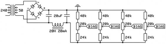
Here's my bias supply. Should work ok I think... I find the 20k pots a little oversensitive at the moment, so I've put some resistors in above and below to narrow the adjustment range, to between -30V and -45V. Hopefully I've got my sums right! Decided against regulating at the moment, i think....maybe....
Cheers,
Steve
Attachments
- Status
- This old topic is closed. If you want to reopen this topic, contact a moderator using the "Report Post" button.
- Home
- Amplifiers
- Tubes / Valves
- My new pp KT88 design