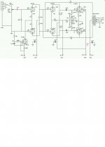
In my amp (please see attached schema), I have an input stage consisting of a 6SL7 LTP splitter with 6AU6 CCS in the tail. The 6SL7 grids are at ground potential (=0v). The 6AU6 plate is connected to the cathodes of the 6SL7 LTP, there is -22v on the screen, the cathode goes to a -122v rail via 660 ohm resistor and the control grid is connected directly to the -122v rail. This arrangement causes the 6AU6 to draw 3mA, shared approximately between the plate and screen grid in the ratio of 2:1, so its plate current is about 2mA.
From the above, each half of the 6SL7 is passing about 1mA. Because I have a DC connection between the 6SL7 plates and the grids of the following 6SN7 drivers, I have kept the 6SL7 pate voltage low, at 78v. According to the 6SL7 curves, this should mean that there is a grid bias of about -0.75v. Am I correct in thinking that the maximum input signal that this stage can tolerate without clipping would be = 0.75/1.414 = 530mV RMS? (If so, I guess it means that I need sufficient overall gain in the amp to get full output with this magnitude of signal).
From the above, each half of the 6SL7 is passing about 1mA. Because I have a DC connection between the 6SL7 plates and the grids of the following 6SN7 drivers, I have kept the 6SL7 pate voltage low, at 78v. According to the 6SL7 curves, this should mean that there is a grid bias of about -0.75v. Am I correct in thinking that the maximum input signal that this stage can tolerate without clipping would be = 0.75/1.414 = 530mV RMS? (If so, I guess it means that I need sufficient overall gain in the amp to get full output with this magnitude of signal).
Attachments
ray_moth said:In my amp (please see attached schema),
. . .
From the above, each half of the 6SL7 is passing about 1mA. Because I have a DC connection between the 6SL7 plates and the grids of the following 6SN7 drivers, I have kept the 6SL7 pate voltage low, at 78v. According to the 6SL7 curves, this should mean that there is a grid bias of about -0.75v. Am I correct in thinking that the maximum input signal that this stage can tolerate without clipping would be = 0.75/1.414 = 530mV RMS? (If so, I guess it means that I need sufficient overall gain in the amp to get full output with this magnitude of signal).
Mmmh, yes, most probably twice that value ( +/- 0.75v).
I could suggest to further reduce the current in the 6SL7, but 1mA seems a reasonnable value and, doing so will induce changing the value of plate resistor too, with incidences on the feed back

I wonder about removing the two 1K in the cathodes, better or worst

Yves.
The problem here is that the plate voltage is low and the current is (relatively) high at 1mA. I presume this means a very low bias point, which will tolerate only a very low signal level. I think removing the cathode resistors from the 6SL7 would simultaneously increase its transconductance and reduce the cross-coupled negative feedback. The end result of that would be a much more sensitive amplifier, in which the low bias point would probably be OK. However, it would be more prone to noise and the volume control would have to be set at a low level. The damping factor would also suffer and with pentodes that could be a problem
What I might try is introducing a Van Scoyoc splitter in place of the LTP, enabling me to get rid of the tail CCS, doubling the gain and using the whole of B+ and B- for the first stage.
What I might try is introducing a Van Scoyoc splitter in place of the LTP, enabling me to get rid of the tail CCS, doubling the gain and using the whole of B+ and B- for the first stage.
78V is awfully low for a 6SL7. Why not bite the bullet and change out the tube CCS for a couple of bipolars, then since you're already cap coupling at the input, reference the first stage to one of the B- rails? That will let you get the effective B+ up another 100V or so without penalizing the 6SN7 or having to live with the intrinsic (mu+1)/mu imbalance of a cross coupled inverter.
Also, you'll want some protection diodes from the grid to cathode of each 6SN7.
Also, you'll want some protection diodes from the grid to cathode of each 6SN7.
I'm quite attached to my pentode CCS - it worked first time I tried it and the current was what I had planned (beginner's luck?). The only time I've tried SS CCS in a tube circuit, I've exerienced instant failure of the devices.
I know what you mean, though, and the best way I can think of to give the 6SL7 a decent plate-cathode voltage, like at least 200v, is to abandon the idea of direct coupling (which gives me a large difference in plate voltage on the 6SN7 anyway) and to use a step-network instead, down to the negative rail, thereby giving the 6SN7 driver a lower grid voltage. Using the negative rail for the 6SN7 cathode retrun should allow me to use a reasonably large tail resistor.
I didn't realize thast was a problem. What causes it?
I know what you mean, though, and the best way I can think of to give the 6SL7 a decent plate-cathode voltage, like at least 200v, is to abandon the idea of direct coupling (which gives me a large difference in plate voltage on the 6SN7 anyway) and to use a step-network instead, down to the negative rail, thereby giving the 6SN7 driver a lower grid voltage. Using the negative rail for the 6SN7 cathode retrun should allow me to use a reasonably large tail resistor.
. . . the intrinsic (mu+1)/mu imbalance of a cross coupled inverter.
I didn't realize thast was a problem. What causes it?
I used this kind of driver in many format, in my amplifiers. The biggest problem is the DC balance. If the first stage has no absolutely same output voltage, the second stage can go extremly unbalanced, even cut off...
I'm not familiar with 6SL7. I used E88CC+ECC99 in my amplifier to drive triode connected 6550s. The E88CC used with 60V plate, and 2mA bias, the ECC99 with 120V plate, and 8mA bias. It sounds great. But for reliability You need to use cathode resistors for the first, and for the second LTP stages too.
I not used ccs, but simple cathode resistors, and AC balance was almost perfect without any settings.
To set the DC balance, I used simple network to add some DC offset for the grid of the first triode, at the AC feedback point (pin4 of the 6SL7). It's easy to apply, and You can set perfect DC balance for every tubes.
sajti
I didn't realize thast was a problem. What causes it?
It's easier to explain with a drawing and I'm not near a scanner. But basically, the output signal on one side rides on top of the input signal, which is not the case for the other side.
Your amplifier has some similarities with my own design. DC stability is a minor problem I'm still working on.
Link to my design
Link to my design
Jax said:Your amplifier has some similarities with my own design. DC stability is a minor problem I'm still working on.
Link to my design
I had same problem, with this configuration. My solution was the following:
1, Use small resistors at the cathodes for every triodes. 100-470ohms, ore more. This will reduce the overall gain, but for DC gain too. Resistors are also important for the second stage. It can handle more offset with that resistors.
2, I don't like to use trimmer in the cathode, of the input stage. I used regulated DC to the grid of V1b (feedback point). It's easy to make with two zeners, trimmer, and series resistor. This solution has no influence to the AC balance.
3, Use regulated voltage for the input stage. It has not too much bias, so simple zener regulator do the regulation. It will help to get stable plate voltage.
sajti
- Status
- This old topic is closed. If you want to reopen this topic, contact a moderator using the "Report Post" button.
- Home
- Amplifiers
- Tubes / Valves
- IP headroom with LTP splitter