What you asked about:
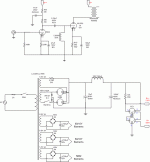
It'll work, but it puts the switch at AC volts. It'll work better in the ground line.
What you didn't ask about:
1. Typically, the jumpers inside the 0C3s are used to protect the REGULATED output, not an unrelated load. Especially in this case, the output tube will experience no ills if a regulator tube is removed. However, the preamp stage will be overvoltaged, which I would assume (given the purported need for regulation) will cause it to smoke. But that isn't true either, because it's just a preamp stage, that has no need of regulation.
2. Yikes, a capacitor (47uF) after a gas regulator! 1k is probably enough to decouple it, but it insults the regulator tubes by saying to them, "oh I like what you do, but I like my way better and I'm going to filter ANYWAY, neener neener!
  ".
". 
Tim, sighing at the contradictions and malpractice of "audiophiles"
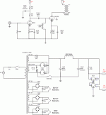
It'll work, but it puts the switch at AC volts. It'll work better in the ground line.
What you didn't ask about:
1. Typically, the jumpers inside the 0C3s are used to protect the REGULATED output, not an unrelated load. Especially in this case, the output tube will experience no ills if a regulator tube is removed. However, the preamp stage will be overvoltaged, which I would assume (given the purported need for regulation) will cause it to smoke. But that isn't true either, because it's just a preamp stage, that has no need of regulation.
2. Yikes, a capacitor (47uF) after a gas regulator!

Tim, sighing at the contradictions and malpractice of "audiophiles"
Hi Tim,
Thanks for dropping by and as always, I learn from you.
1. I have made changes to the stand by in the attached diagram. Is that what you meant it should be?
2. The use of 2 x 0C3 was primarily for clamping the voltage to 210V regardless of the power tube in. When a 10Y tube is in this circuit, my B+ will be higher as compared to when a 50 is in the circuit. I need around 170V for the 5842 drivers regardless of the power tube in circuit. I was thinking of separate transformer for the driver, but I don't have space at the moment. Aside from another transformer, can you show me better way?
3. I'll just take out the 47uF after the 1k8 dropping resistor. I'm dropping around 40V here.
I just pasted these ideas together from the replies in my previous thread
I appreciate your help, as usual
Attachments
arnoldc said:1. I have made changes to the stand by in the attached diagram. Is that what you meant it should be?
Yep, that'll do.
2. The use of 2 x 0C3 was primarily for clamping the voltage to 210V regardless of the power tube in. When a 10Y tube is in this circuit, my B+ will be higher as compared to when a 50 is in the circuit. I need around 170V for the 5842 drivers regardless of the power tube in circuit.
Hrm, where'd you get the driver from? How much drive does the output need? I wouldn't run my driver from +170V even if it were driving 6V6's!
If power supply sags so dramatically, how does the fixed bias resistor fare? Do the two types happen to use the same resistance, just different bias voltage and current?
And if your power supply sags so dramatically... seems a good argument to switch those 5AR4's to 1N4007's...
I was thinking of separate transformer for the driver, but I don't have space at the moment. Aside from another transformer, can you show me better way?
Well, unless it sags more than 50V (10%), I would say a dropping resistor and capacitor is fine. It's a driver circuit, not an oscilloscope.
Tim
Thanks!Sch3mat1c said:Yep, that'll do.
From ThorstenHrm, where'd you get the driver from? How much drive does the output need? I wouldn't run my driver from +170V even if it were driving 6V6's!
When operating in 50 mode, the 2K2 and 3k3 is paralleled giving 1430 ohms, when in 10Y mode, only the 2k2 is connected.If power supply sags so dramatically, how does the fixed bias resistor fare? Do the two types happen to use the same resistance, just different bias voltage and current?
The difference will be around 30V, so I hear you Tim.Well, unless it sags more than 50V (10%), I would say a dropping resistor and capacitor is fine. It's a driver circuit, not an oscilloscope.
Thanks again. Now it becomes much simpler

Konnichiwa,
But you overlooked that I am talking "Anode Load Choke", in which case C=B ~ Va. You use a resistor load and thus you need to add Ia * Ra to the Voltage on the Anode to get the +B for the stage. In the case of suggested 170V/12mA for the 417A with your shown 15K anode load you need 350V as Supply voltage.
In order to make that then work with a +420V main supply you need a 5K6 decoupling resistor in the +B line to the Driver Stage.
Also be aware that using the 5687 with a resistor load may limit your available anode swing to less than you need, best get the curves out and draw in a nice loadline and see where that gets you to.
Sayonara
arnoldc said:From Thorstenbased on the discussions here - http://www.diyaudio.com/forums/showthread.php?threadid=48999
But you overlooked that I am talking "Anode Load Choke", in which case C=B ~ Va. You use a resistor load and thus you need to add Ia * Ra to the Voltage on the Anode to get the +B for the stage. In the case of suggested 170V/12mA for the 417A with your shown 15K anode load you need 350V as Supply voltage.
In order to make that then work with a +420V main supply you need a 5K6 decoupling resistor in the +B line to the Driver Stage.
Also be aware that using the 5687 with a resistor load may limit your available anode swing to less than you need, best get the curves out and draw in a nice loadline and see where that gets you to.
Sayonara
- Status
- This old topic is closed. If you want to reopen this topic, contact a moderator using the "Report Post" button.
- Home
- Amplifiers
- Tubes / Valves
- My 50/10Y amp with hybrid PSU... am I doing the standby switch right?

