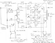
OK, i wipped up a preliminary map... power supply details missing (Scott i know you will likely end up with Solen poly caps in the PS), and it may need some cathode bypass Rs (i know your OPTs are high Z so maybe we can get away without -- if we can the amp will have no electrolytics in it)
dave
dave
Attachments
RH ECL86
Thanks Dave:
This is exactly where I want to go. I will measure the PS transformer of my donor so we can work out the operating voltages.
You indicate SS rectification what about tubes?
Can you send this to Chris. He was getting a solens order ready and I may as well get the caps now if you can come up a good guess for the values. If not i can wait for the next order.
Thanks again
Re: RH ECL86
An EZ81 can be subbed in for 2 of the diodes... there will be a tad less B+, but so far that has worked out OK.
Chris & i talked about that yesterday ...
dave
SCD said:You indicate SS rectification what about tubes?
An EZ81 can be subbed in for 2 of the diodes... there will be a tad less B+, but so far that has worked out OK.
I may as well get the caps now if you can come up a good guess for the values. If not i can wait for the next order.
Chris & i talked about that yesterday ...
dave
Re: Schematic as requested bt SCD
Is that how you actually built it... the FB R goes from the plate of the output tube to the top of the input tube plate resistor (as opposed to the plate of the tube)?
dave
gingertube said:Gingertubes variant of the original Shunt Feedback Push Pull.
Is that how you actually built it... the FB R goes from the plate of the output tube to the top of the input tube plate resistor (as opposed to the plate of the tube)?
dave
Dave,
Yep - thats how I actually built it. The 2 x 47K + 12K provides (I think) parallel shunt feedback and a degree of self AC balancing. As I've repeatedly stated the sound is just stunning. Thats why I've been trying to interest a few of the more experienced folks here to see if they can offer insights as to why it might perform so well. The current source I used on the input diff amp is pretty basic and could be improved (cascode with LED reference etc.) BUT as it is it works brilliantly. No B.. S... I've disconnected my 845SET to listen to this instead.
Yves Monmagnon's original circuit used fixed bias, had no UL taps and used global feedback. My circuit was unstable with global feedback BUT I did'nt feel it needed it so did'nt go looking for the cause/fix.
My musings are: The feedback is applied to the top of the input triode load resistors with very low source resistance (there is a virtual earth at about the centre of the 12K resistor - so source resistance should be about 6K - this shifts with AC imbalance on the output anodes, hence my theory that there is some inherent self AC balancing). The 12K means I think that is no longer the "partial feedback" scheme but something else - feedback being applied via the diff amp power supplies ????
Oh - the O/P trannies I used are about 5600:3.5 with 20% UL (rather than the more usual 43%) taps. This would normally be a bit low on Raa for ECL86 - my speakers are nominally 6 Ohms so that would be helping to get load on the O/P sections up a bit.
I really would like to hear from anyone with an explaination of what the 2 x 47K + 12K is doing - do you agree with my musings?am I talking rubbish?
Cheers,
Ian
gingertube said:I really would like to hear from anyone with an explaination of what the 2 x 47K + 12K is doing - do you agree with my musings?
I agree that it is different from the RH scheme... what it is doing is beyond me (i still consider myself a rookie)... lets see if we can get some comments from some who might know.
dave
My take on the AC potential divider
Agreed, the 12k and 2 x 47k idea assists AC balance, and there will be a virtual earth at the centre of the 12k. In that respect it's like the floating balanced audio used by professionals.The exact value of that 12k resistor adjusts the amount of AC feedback independently of the DC conditions (which is nice) - a short circuit in place of the 12k would remove the feedback but would still have a balancing action (imagine one output valve not producing a signal). All in all, interesting. Might have to experiment.
Agreed, the 12k and 2 x 47k idea assists AC balance, and there will be a virtual earth at the centre of the 12k. In that respect it's like the floating balanced audio used by professionals.The exact value of that 12k resistor adjusts the amount of AC feedback independently of the DC conditions (which is nice) - a short circuit in place of the 12k would remove the feedback but would still have a balancing action (imagine one output valve not producing a signal). All in all, interesting. Might have to experiment.
Hi Ian !
It would be difficult for me to disagree with you, specially when you seem so happy !
I don't know if the words "partial feedback" are somewhat "reserved" for a specific structure, but as long as we have a feedback loop wich is not global, how must we call it ? "local feedback" ?
To add a word about the schemo, all started in wondering what I could do with this box of 25 ECL86 sleeping on a shelf.
Gain of both sections was so high, and I didn't want to rely on a -difficult to manage- huge amount of global feedback.
For subjective reasons, I chosed to use an LTP PI rather that a concertina, and, at first, I used two anode resistors for each triode anode, each to a different plate of the output stage.
This worked, but it was not easy to adjust the degree of feedback without changing 4 resistors.
That's why I used that "divider" between final tubes's plates.
So, just altering the 12K sets the amount of feedback you want, without any effect on static working point.
Completly removing that resistor returns to the so called "partial feedback"
Finally, it's like if the PI anodes was returned to two "adjustable" taps on the OPT primary.
I don't see any reason for applying that "divider" method into a SE design.
The 47K must be of at least 3W types, not for the power inside, but for the AC voltage accross'em.
Small units don't like that and may even become unlinear.
And, yes, AC balance is certainly improved too (To the tolerance of the resistors of course).
Perhaps, as you didn't implemented global NFB, the damping of the loudspeakers is lower (cos OPT's copper losses are not "hidden" by the NFB) and this, specially with "bass reflex", may increase the level at lo frequency.
This is manageable by choosing a proper balance of local and global NFB, just two resistors to adjust !
Of course this heavily depend of the match between 3 factors: The OPT, the loudspeaker system and ... your ears.
Did you find THE good macth ?
My faith is " a pinch of NFB everywhere rather than a shovelful anywhere " !
Like salt and pepper (Remember, we, froggies, are cooking too) !
Oh, gimme a pleasure, my name spells "Yves Monmagnon" ;>)
Yves
P.S.
While typing this post, EC8010 confirmed some of my thoughts !
OT, EC8010 : Are there places in London that a tube lover MUST visit (while my wife and kids will admire Tower Bridge, three weeks from now) ?
London - awful place.
Yves,
sadly, if you mean "Are there any wonderful junk shops tended by octogenarians and stacked high with boxes of NOS KT66 and Williamson output transformers?" then the answer is no. In fact, I'm not sure that there are any proper junk shops left. I do hope someone can disagree with me on this one...
There are a few wonderful pubs in London but my inability to give directions is only exceeded by my ability to get lost trying to find them. Nevertheless, a quick look at my Good Pub Guide says that there's a good pub near Tower Bridge called "Pommelers Rest" - try the Fuller's "London Pride".
More musings on this schematic
The balanced shunt feedback will be correcting the pentodes behaviour. At the same time there will be some dynamic "anti-bootstap" effect on the anode loads of the diff amp (making them look smaller than 220K) - thus emphasising triode like response and coupling some of that behaviour into the feedback loop around the pentodes.
This has been attempted before with a real triode in the feedback path but never so simply and dare I use the word "elegantly".
I have been listening to this little amp for 2 weeks now - Its not the ultimate in valve amplification but for a pair of ECL86s (6GW8s) it is stunning and leaves my Rogers Cadet III (the only other ECL86 Push Pull Amp I have) for dead.
Anyone else want to have a go at analysis of this wonderful little circuit or comment on the above?
Cheers,
Ian
BTW: If you are intending to build one of these for yourself the current source on the diff amp cathodes could be considerably improved over the simple ring of two circuit. Even a single transistor and LED reference should be better. If you are using the current source as drawn then there is a resistor missing between the reference transistor collector and ground - anything between 10K and about 100K should do.
Re: More musings on this schematic
How much current does the triode diff pair need to draw... i was thinking of using the IXYS 3-pin CCS but am concerned that i might not be able to set it low enuff.
dave
gingertube said:BTW: If you are intending to build one of these
How much current does the triode diff pair need to draw... i was thinking of using the IXYS 3-pin CCS but am concerned that i might not be able to set it low enuff.
dave
Dave,
Yves original circuit had the diff pair current set at 1mA (ie 0.5mA each triode). Mine worked at about 1.2mA total. You would not want to take this much above that value ie say 1.5mA as a maximum limit or 0.75mA per tube without some component value changes.
You need to be a bit cautious about component changes - in particular the circuit arrangement particularly suits the ECL86 (6GW8) with its high gain pentode and triode sections. I would not expect it to work quite as well with say a 6BM8 where both triode and pentode sections are lower gain.
Cheers,
Ian
gingertube said:Yves original circuit had the diff pair current set at 1mA (ie 0.5mA each triode). Mine worked at about 1.2mA total. You would not want to take this much above that value ie say 1.5mA as a maximum limit or 0.75mA per tube without some component value changes.
Back to the drawing board....
dave
gingertube said:Dave,
Yves original circuit had the diff pair current set at 1mA (ie 0.5mA each triode). Mine worked at about 1.2mA total. You would not want to take this much above that value ie say 1.5mA as a maximum limit or 0.75mA per tube without some component value changes.
Try to stay at such lo current, unless you will need to reduce plate load resistor or accept a lower anode voltage for the triodes.
Both seem bad to me.
Cheers, Yves.
Yvesm said:Try to stay at such lo current, unless you will need to reduce plate load resistor or accept a lower anode voltage for the triodes.
Both seem bad to me.
Hence GaryP's use of a high Rp pentode as the input stage in his partial feedback amp. The idle current can be adjusted fairly independently of the anode voltage. Additionally, the local feedback works more freely with the high source resistance presented by a pentode stage.
jeff mai said:high Rp pentode
pentodes were where my mind started going... don't know if what i have handy is suitable... got lots of EF89s and who knows what else, haven't paid much attention to the small signal pentodes in my collection.
dave
jeff_mai
I'm not sure that that is relevant to this circuit. The 12K modifies things from the usual scheme in that the feedback is being applied to the top of the triode load resistor from a relatively low source resistance (about 12K/2=6K because there will be a virtual earth in about the centre of the 12K resistor). One of the beauties of this scheme. The other being the relative divorcing of AC and DC conditions compared to the more usual scheme where the DC rail voltage had to be large enough to accommodate the pentode anode peak AC + the triode anode peak AC + the triode operating voltage.
Cheers,
Ian
Re: jeff_mai
It is getting late... i thought Jeff was talking about the CCS... (that is where i was thinking pentode)
dave
gingertube said:I'm not sure that that is relevant to this circuit
It is getting late... i thought Jeff was talking about the CCS... (that is where i was thinking pentode)
dave
jeff mai said:
Hence GaryP's use of a high Rp pentode as the input stage in his partial feedback amp. The idle current can be adjusted fairly independently of the anode voltage. Additionally, the local feedback works more freely with the high source resistance presented by a pentode stage.
I must agree, but I wanted to play with 6GW8 and I've found this twist
")
Look at the just opened thread about a 845 SE project I intend to drive with such topology.
Yves.
- Status
- This old topic is closed. If you want to reopen this topic, contact a moderator using the "Report Post" button.
- Home
- Amplifiers
- Tubes / Valves
- Hey Planet_10 (and others)