Hi,
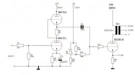
If R1 is meant as a gridstopper it should be positioned as close to the grid of the 6SL7 as possible.
As it is now it will attenuate the incoming signal slightly, I doubt you'd want that.
The B+ voltage probably will have risen a little but that shouldn't be an issue in practice.
Other than that, it should work just fine.
Ideally, that's what I'd do anyway, I'd drive the 6C33-C from a 6SN7GTB in SRPP and ommit the cathode bypass cap if I'd be using a line level preamp with gain to spare.
Cheers,")
If R1 is meant as a gridstopper it should be positioned as close to the grid of the 6SL7 as possible.
As it is now it will attenuate the incoming signal slightly, I doubt you'd want that.
The B+ voltage probably will have risen a little but that shouldn't be an issue in practice.
Other than that, it should work just fine.
Ideally, that's what I'd do anyway, I'd drive the 6C33-C from a 6SN7GTB in SRPP and ommit the cathode bypass cap if I'd be using a line level preamp with gain to spare.
Cheers,
If you are looking for 6c33 designs then here is another
http://www.audiopro.co.jp/foxbatk.jpg
Andrew
http://www.audiopro.co.jp/foxbatk.jpg
Andrew
FrancoB said:Please comment. Original design is from jogis-roehrenbude.de But there's too much gain to drive it with a preamp. I stripped the first stage of the original design.
Too much gain: add attenuator (volume control or fixed divider) or use lower gain tube. 6SN7 was mentioned, that'll work. You'll want a bit more current, so smaller resistors in the SRPP stage will be needed. <Glances around> I'll let someone else figure exactly what values are needed...or pick 'em off something existing... /ducks out of thread
Tim
- Status
- This old topic is closed. If you want to reopen this topic, contact a moderator using the "Report Post" button.