The main question is:
How can I have 6Vdc from 6,3Vac?
I’d like to feed the filaments of my 12B4A preamp with DC. And power transformer has only 6,3Vac CT winding, 5Vac CT for the rectifier and the HT.
I don’t like to add a separate transformer (the best solution) because there’s no space in my chassis.
So, I was trying to find other solutions for that. But I’m not sure if they are correct.
Over here I need your help.
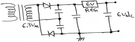
First thought is to use a voltage doubler and a 6V regulator. Sth like the attached schem.
How can I have 6Vdc from 6,3Vac?
I’d like to feed the filaments of my 12B4A preamp with DC. And power transformer has only 6,3Vac CT winding, 5Vac CT for the rectifier and the HT.
I don’t like to add a separate transformer (the best solution) because there’s no space in my chassis.
So, I was trying to find other solutions for that. But I’m not sure if they are correct.
Over here I need your help.
First thought is to use a voltage doubler and a 6V regulator. Sth like the attached schem.
Attachments
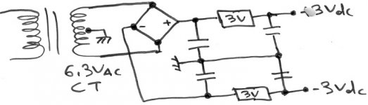
+/- supply is useless. Ground in the circuit is floating for one, putting the regulator grounds in series. Probably a good way to make smoke.
6.3VAC > FWB (schottky if necessary) > resistor > heaters will work just fine. About 2000uF/ampere before and after the resistor.
A regulator is not necessary but if you must, there is enough overhead to use a 7806 (or any lower voltage type with the proper ground elevation).
FWIW, before you try DC heaters, try grounding a resistor divider, or better still than grounding, elevate it a few volts above the highest cathode voltage (if possible). 80% of the time, any hum in the circuit is from insufficient PSU filtering, ground loop or power transformer > heater-cathode pickup (which this cures). The remaining 20% (or maybe less, whichever) are highly sensitive circuits (either small signal or high precision) which DO actually need DC or regulated heater supply.
Tim
Hi there......the power tubes wouldn't know AC from DC....unless a real htr-cath short existed.
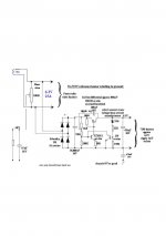
I regulary DC'er my front ends....to advantage. Circuit enclos....a scrounge low dissipation circuit using SB series schottky diodes and very low dropout (0.3V in/out diff) which has been around for eons. The 6.3V AC rects to around 8-9V which is more than enough.
richj
I regulary DC'er my front ends....to advantage. Circuit enclos....a scrounge low dissipation circuit using SB series schottky diodes and very low dropout (0.3V in/out diff) which has been around for eons. The 6.3V AC rects to around 8-9V which is more than enough.
richj
Attachments
resident said:The main question is:
How can I have 6Vdc from 6,3Vac?
I’d like to feed the filaments of my 12B4A preamp with DC. And power transformer has only 6,3Vac CT winding, 5Vac CT for the rectifier and the HT.
I don’t like to add a separate transformer (the best solution) because there’s no space in my chassis.
So, I was trying to find other solutions for that. But I’m not sure if they are correct.
Over here I need your help.
First thought is to use a voltage doubler and a 6V regulator. Sth like the attached schem.
I just converted my preamp heaters from AC to DC. All I did was run the 6.3V into a bridge I had and then into a CRC filter using a 1.8 ohm resistor to bring the voltage back down to 6.3. For the caps I used a couple of 1000uF 50V electrolytics I had in the bin. That's it. It got rid of the hum I had previously and everything seems to be functioning flawlessly.
Re: Re: 6Vdc from 6,3Vac
Yup..... thats the other method I used. Except where I live the AC mains varies +/-10% nom 230V.....with direct AC the lower limit would underun the heaters.
richj
Sherman said:
All I did was run the 6.3V into a bridge I had and then into a CRC filter using a 1.8 ohm resistor to bring the voltage back down to 6.3.
Yup..... thats the other method I used. Except where I live the AC mains varies +/-10% nom 230V.....with direct AC the lower limit would underun the heaters.
richj
resident,
You were on the path to a "simple" solution, when you mentioned voltage doubler. If the RMS current capability of the 6.3 VAC filament winding is 4X the draw of the 12B4's heater when wired for "12" V., you are home nearly free. 6.3 V. RMS is 8.9 V. peak. Doubling that gets you to nearly 18 V. That's more than enough headroom for a modest cost 7812 3 terminal regulator. Put a 10 muF. 'lytic in close proximity to the regulator across its O/P. Put a 2nd 10 muF. 'lytic paralleled by a 10 nF. ceramic part across the heater connections at the socket.
You were on the path to a "simple" solution, when you mentioned voltage doubler. If the RMS current capability of the 6.3 VAC filament winding is 4X the draw of the 12B4's heater when wired for "12" V., you are home nearly free. 6.3 V. RMS is 8.9 V. peak. Doubling that gets you to nearly 18 V. That's more than enough headroom for a modest cost 7812 3 terminal regulator. Put a 10 muF. 'lytic in close proximity to the regulator across its O/P. Put a 2nd 10 muF. 'lytic paralleled by a 10 nF. ceramic part across the heater connections at the socket.
If you feel that you must use DC (as Schematic pointed out, it is rarely necessary), use a simple schottky full wave rectifier, a CRC filter, and put a 6.2V zener diode across the heater terminals.
That's a simple way to get the desired regulation, and well within the voltage tolerance of most valves.
That's a simple way to get the desired regulation, and well within the voltage tolerance of most valves.
Thanks everybody for your help!
So there’s solution.I like very much Tim’s idea.
As I understand, use a resistor divider from HT to ground and from the joint of the two resistors feed the heaters. About how many volts?
I will not ground the CT of the heaters winding,right?
If this doesn’t work,I’ll go dc just like that.
........I think I'm thinking too complex ..........
So there’s solution.I like very much Tim’s idea.
As I know AC sounds better than DC!FWIW, before you try DC heaters, try grounding a resistor divider, or better still than grounding, elevate it a few volts above the highest cathode voltage (if possible).
As I understand, use a resistor divider from HT to ground and from the joint of the two resistors feed the heaters. About how many volts?
I will not ground the CT of the heaters winding,right?
If this doesn’t work,I’ll go dc just like that.
or6.3VAC > FWB (schottky if necessary) > resistor > heaters will work just fine. About 2000uF/ampere before and after the resistor.
use a simple schottky full wave rectifier, a CRC filter, and put a 6.2V zener diode across the heater terminals.
........I think I'm thinking too complex
..........Grounded means two things, AC or DC. Just remember that you want the center of the heaters grounded, if just AC-wise. So a bypass cap, say 10uF tacked on that voltage divider will do well. If you don't have a hum balance pot or CT on the winding, use two 100 ohm resistors to obtain a center tap.
I wouldn't recommend a 6.2V zener because it could draw a *lot* of current if voltage rises too much. Things could get very messy, very fast. Not to mention it likewise has to be rated a good bit of current... 1W need not apply! A 7806 is perfect, though cold heater surge current might upset it; a resistor, however, is current limited and adds filtering (though no regulation, +/-10% is good enough for tubes).
Or if that 5VAC winding is going unused and is rated for the current, a FWB on that might work right off the bat, no resistor or regulator needed!
Tim
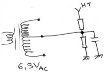
I have attached a pic.Hope it's something like this.
But,how many volts must I apply to filaments?
Ht is around 250V.
Smart thinking though.I'll know it for future projects.
But,how many volts must I apply to filaments?
Ht is around 250V.
I have a tube rectifier.So I need this winding.Or if that 5VAC winding is going unused and is rated for the current, a FWB on that might work right off the bat, no resistor or regulator needed!
Smart thinking though.I'll know it for future projects.
Attachments
resident said:I have attached a pic.Hope it's something like this.
But,how many volts must I apply to filaments?
Correct.
What are the cathode voltages in your amp? You want heater at least a few volts above the highest, but only if it doesn't exceed any H-K ratings. If that becomes an issue, then somewhere between will suffice.
Tim
OK....it's not so simple.If I'd like to try CF...just take the output from the cathode,right?
Tim,Grounded means two things, AC or DC. Just remember that you want the center of the heaters grounded, if just AC-wise. So a bypass cap, say 10uF tacked on that voltage divider will do well. If you don't have a hum balance pot or CT on the winding, use two 100 ohm resistors to obtain a center tap.
Suppose R1 is the upper resistor and R2 the other (I'm reffering to the voltage divider in my pic).
How much must be the total resistance of the voltage divider?
R1+R2= ?
- Status
- This old topic is closed. If you want to reopen this topic, contact a moderator using the "Report Post" button.
- Home
- Amplifiers
- Tubes / Valves
- 6Vdc from 6,3Vac