6CG7/5687/2A3PP amp
Well, there I am up and going.
The voltages was pretty much as expected on the first try.
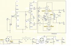
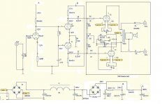
With 470R cathode resistors I get a anode voltage on the 6CG7 to be 92V.
So I changed the resistors to 345R and the anode voltage decreased to 82-83V.
I then have only 1,5V on the cathode of the 6CG7. Is this enough or should I change the cathode resistors back again to 470R? (which gave a cathode voltage of 1,9V).
I see that not all are so easy to read on the attched schematic so:
- The voltage out of the new rectifier are 390V which gives 374V on top of the anoderesistor for the 5687 and about 200V on the anode on the 5687.
- The voltage on the top of the anode resistor for the 6CG7 are 368V.
Well, there I am up and going.
The voltages was pretty much as expected on the first try.
With 470R cathode resistors I get a anode voltage on the 6CG7 to be 92V.
So I changed the resistors to 345R and the anode voltage decreased to 82-83V.
I then have only 1,5V on the cathode of the 6CG7. Is this enough or should I change the cathode resistors back again to 470R? (which gave a cathode voltage of 1,9V).
I see that not all are so easy to read on the attched schematic so:
- The voltage out of the new rectifier are 390V which gives 374V on top of the anoderesistor for the 5687 and about 200V on the anode on the 5687.
- The voltage on the top of the anode resistor for the 6CG7 are 368V.
Attachments
Re: 6CG7/5687/2A3PP amp
Konnichiwa,
You are spot on. What does it sound like to you?
Ciao T
Konnichiwa,
Taffi said:So I changed the resistors to 345R and the anode voltage decreased to 82-83V.
I then have only 1,5V on the cathode of the 6CG7. Is this enough or should I change the cathode resistors back again to 470R? (which gave a cathode voltage of 1,9V).
You are spot on. What does it sound like to you?
Ciao T
Re: Re: 6CG7/5687/2A3PP amp
Konnichiwa,
On second thought, the 5687 Anodes are a little low in Voltage, try an 18K common Cathode Resistor to make sure things fall into place.
Ciao T
Konnichiwa,
Kuei Yang Wang said:You are spot on.
On second thought, the 5687 Anodes are a little low in Voltage, try an 18K common Cathode Resistor to make sure things fall into place.
Ciao T
Re: Re: 6CG7/5687/2A3PP amp
So this evening I shall compare it to a chinese 6SL7-2A3SE amp that are supposed to be very special.
Report are coming...............
Well, I have not tried it yet (but was very happy for it to work).Kuei Yang Wang said:Konnichiwa,
You are spot on. What does it sound like to you?
Ciao T
So this evening I shall compare it to a chinese 6SL7-2A3SE amp that are supposed to be very special.
Report are coming...............
Re: Re: Re: 6CG7/5687/2A3PP amp
15K athode resistor gives a anode voltage of 220V.
18K gives 250V.
Which shall I go for?
Sorry, but I guess I did not get the measurments correct the first time.Kuei Yang Wang said:Konnichiwa,
On second thought, the 5687 Anodes are a little low in Voltage, try an 18K common Cathode Resistor to make sure things fall into place.
Ciao T
15K athode resistor gives a anode voltage of 220V.
18K gives 250V.
Which shall I go for?
Re: Re: Re: Re: 6CG7/5687/2A3PP amp
Konnichiwa,
Go for 18K. With 250V on the Anode you have around 160V Anode/Cathode and you need around 45...50V swing, so you'll be having good linearity.
Ciao T
Konnichiwa,
Taffi said:Sorry, but I guess I did not get the measurments correct the first time. 15K Cathode resistor gives a anode voltage of 220V.
18K gives 250V. Which shall I go for?
Go for 18K. With 250V on the Anode you have around 160V Anode/Cathode and you need around 45...50V swing, so you'll be having good linearity.
Ciao T
I have now played for some hours and the amp sounds GREAT!
Clearly better than ever before.
It sounds big, spacious,fast, open, detailed, smooth, dynamic and neither overly warm or overly bright.
So I am VERY satiesfied with the 6CG7/5687/2A3PP configuration.
IF I should want more it would have been some more grunt and punch in the bass.
This amp have IMHO always sounded a little light in the bass (but the bass is else of high quality), whatever which configuration I have used.
So my guess is that I have to do something about the power supply to get the bass stronger.
Problem is that I do not have much space inside the amp and I am afraid that the only possible solution is to make a outboard power supply (which of course is a lot of work).
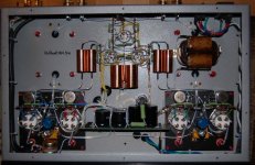
Btw. all signal caps are Mundorf silver in oil.
Power supply caps are Audio Note and Rubicon.
Resistors are mosly 2W Beychlag, but also some 1W Kiwame.
Tubes are Sovtek 2A3's, Heinz & Kaufmann 5687's and RCA clear top 6CG7.
Clearly better than ever before.
It sounds big, spacious,fast, open, detailed, smooth, dynamic and neither overly warm or overly bright.
So I am VERY satiesfied with the 6CG7/5687/2A3PP configuration.
IF I should want more it would have been some more grunt and punch in the bass.
This amp have IMHO always sounded a little light in the bass (but the bass is else of high quality), whatever which configuration I have used.
So my guess is that I have to do something about the power supply to get the bass stronger.
Problem is that I do not have much space inside the amp and I am afraid that the only possible solution is to make a outboard power supply (which of course is a lot of work).
Btw. all signal caps are Mundorf silver in oil.
Power supply caps are Audio Note and Rubicon.
Resistors are mosly 2W Beychlag, but also some 1W Kiwame.
Tubes are Sovtek 2A3's, Heinz & Kaufmann 5687's and RCA clear top 6CG7.
Konnichiwa,
Thank you for the feedback. Good to know that I was able to help a little.
But:
This may be at least partially related to the output Valves.
There are no circuit element that IMHO prejudice good bass output except possibly the Output Transformer, which should be good enough as well.
What sort of speakers are you using? You might want to try the 4 Ohm Tap.
Can you measure the actual LF frequency response you are getting?
You could try adding capacitance to the second filter capacitor in the main PSU, but I doubt this would improve things that much.
Sayonara
Taffi said:I have now played for some hours and the amp sounds GREAT!
Clearly better than ever before.
It sounds big, spacious,fast, open, detailed, smooth, dynamic and neither overly warm or overly bright.
So I am VERY satiesfied with the 6CG7/5687/2A3PP configuration.
Taffi said:Just a few more words about the sound.
The amp has some kind of smooth musical flow that really are great. This is IMHO a very musical sounding sounding amp.
Thank you for the feedback. Good to know that I was able to help a little.
But:
Taffi said:IF I should want more it would have been some more grunt and punch in the bass.
This amp have IMHO always sounded a little light in the bass (but the bass is else of high quality), whatever which configuration I have used.
Taffi said:So if I just could have some more bass grunt...... it would be "perfect".
This may be at least partially related to the output Valves.
There are no circuit element that IMHO prejudice good bass output except possibly the Output Transformer, which should be good enough as well.
What sort of speakers are you using? You might want to try the 4 Ohm Tap.
Can you measure the actual LF frequency response you are getting?
Taffi said:So my guess is that I have to do something about the power supply to get the bass stronger.
You could try adding capacitance to the second filter capacitor in the main PSU, but I doubt this would improve things that much.
Sayonara
Konnichiwa,
Some corollary. Pairs of Sovtek 2A3's I had tended to drift over time. The result was that the bias did not remain balanced.
I note that your circuit does not show the two 1M5 resistors from the two ends of the 22K resistor in the Gridleak circuit for the 2A3's to the +B Node which are needed to allow you to balance out the current in the 2A3.
If the current becomes too unbalanced the output transformers primary inductance will fall to fairly low values.
Sayonara
Kuei Yang Wang said:This may be at least partially related to the output Valves.
Some corollary. Pairs of Sovtek 2A3's I had tended to drift over time. The result was that the bias did not remain balanced.
I note that your circuit does not show the two 1M5 resistors from the two ends of the 22K resistor in the Gridleak circuit for the 2A3's to the +B Node which are needed to allow you to balance out the current in the 2A3.
If the current becomes too unbalanced the output transformers primary inductance will fall to fairly low values.
Sayonara
Kuei Yang Wang said:Konnichiwa,
This may be at least partially related to the output Valves.
There are no circuit element that IMHO prejudice good bass output except possibly the Output Transformer, which should be good enough as well.
What sort of speakers are you using? You might want to try the 4 Ohm Tap.
I am using Avantgarde Duo speakers.
Btw. the bass I have are fast and of very high quality. Just missing a little bit punch and power.
You mean by using a test cd or a signalgenerator at the input of the amp and just measure the voltage on the output?Can you measure the actual LF frequency response you are getting?
Can I do so without having the speakers connected but instead use a resistor (5-10R) connected to the amp?
Asking because I do not find the sound coming from my signalgenerator to be exactly my musical taste
")
My experience with adding capacitance have always been that I get a tighter bass by doing so. This is not what I need.You could try adding capacitance to the second filter capacitor in the main PSU, but I doubt this would improve things that much.
Sayonara
In fact I could have lived with a bass that was less tight if this at the same time had give me more power and punch.
The first two caps in the power (C1 and C2) was originally Rubicon 220uF, but has been changed to BK 150uF.
One of the Rubicon's was then used after the new rectifier that I attached..
Btw. I also will try using my active preamp (EAR 834L) with the amp and hear what happens.
And most important:
This is just a minor fault since all in all the amp are playing really good!
I guess you mean the 1M resistors going from on side of R24 to the points marked I2, I3, I6, I7 on the pcb.Kuei Yang Wang said:Konnichiwa,
Some corollary. Pairs of Sovtek 2A3's I had tended to drift over time. The result was that the bias did not remain balanced.
I note that your circuit does not show the two 1M5 resistors from the two ends of the 22K resistor in the Gridleak circuit for the 2A3's to the +B Node which are needed to allow you to balance out the current in the 2A3.
If the current becomes too unbalanced the output transformers primary inductance will fall to fairly low values.
Sayonara
They are there and I can adjust the ballance pots.
Having said that the DC reading that I gets fluctate very much.
Much more than I thought it should have.
The reading going up and down 50mV and sometimes more than that (up to several hundreds mV).
If I measure AC instead it lays around 200mV and this too fluctates a lot (up to 50mV).
The same happens when I measure the hum on the output terminals.
Most of the time it's fairly low at about 1mV, but sometimes there is peaks coming up to 10mV.
When this is said I have never heard any of this peaks making any sound from my speakers and I also do not have any clue on the this happens.
Any idea?
Konnichiwa,
Hmmm, maybe all they need is a slight re-adjustment of the woofer controls?
Also, those belong definitly on the 8 Ohm Output.
Yes, use an 8 Ohm Resistor on the 8 Ohm Outputs. It helps using a power resistor.
Okay, then that part will be okay.
You must short-circuit the input jacks to get this reading sensible.
Sayonara
Taffi said:I am using Avantgarde Duo speakers.
Hmmm, maybe all they need is a slight re-adjustment of the woofer controls?
Also, those belong definitly on the 8 Ohm Output.
Taffi said:You mean by using a test cd or a signalgenerator at the input of the amp and just measure the voltage on the output?
Can I do so without having the speakers connected but instead use a resistor (5-10R) connected to the amp?
Yes, use an 8 Ohm Resistor on the 8 Ohm Outputs. It helps using a power resistor.
Taffi said:I guess you mean the 1M resistors going from on side of R24 to the points marked I2, I3, I6, I7 on the pcb. They are there and I can adjust the ballance pots.
Okay, then that part will be okay.
Taffi said:Having said that the DC reading that I gets fluctate very much.
Much more than I thought it should have.
You must short-circuit the input jacks to get this reading sensible.
Sayonara
Just a little update.
Regarding the bass much of the problems I had turned out to be a problem with my turntable.
I do have more bass punch in both my SS Avantgarde Model 5 amp and my 50kg SE 300B amp, but the bass quality in the 6CG7/5687/2A3 are BETTER than either!
And in overall sound quality the 6CG7/5687/2A3 are one of the best (and maybe THE best) amp I have ever tried (and I have owned or tried hundreds).
For example it's clearly superior (IMHO) to the two above mentioned amps that I also own.
If I use the amp with a EAR 834L preamp (all Mullard tubes) I get better dynamics and punch, but loose some transperancy and also gets some grain.
I am at this point not sure which solution I prefer.
Btw. using the pot at the 6CG7/5687/2A3PP amp at half and at the same time using a preamp to not work good at all.
Regarding tubes I have just tried two different 6CG7's, both RCA.
The RCA clear top are fast and clear and have fantastic PRAT.
I also have an older RCA that is warmer, more fleshed out and fuller sounding with a better midrange, but it can't compare to the clear top when it comes to PRAT.
So for rhytmic music (isn't every music rhytmic?) I absolutely prefer the clear top.
I also have Golden Dragon and EI brand new 6CG7's laying around, but have not tried them yet since for now I just like playing music
For further improvements of the amp I think it have to wait.
The amp sounds so damn good as it is and "never change a winning team" they say
Very interesting this topic, and I decided to rebuild my Joplin Amp. to the same specification. Now I run into a problem. My problem is that there is a hum in the amp. A typical frequency hum, and I think it is the power supply.
Is it possible that I have to use a choke in the upgraded power stage.. (just after the second rectifier bridge )
All the voltages thruout the schematic are the same as in the schematic of Taffi.
First rec.bridge - first condensator 220mf - choke - condensator 220mf - 2nd rec. bridge - condensator 220 mf - resistor1 - resistor2, both with 47mf condensator.
If I disconnect the 70V AC from the 2nd bridge, the hum is gone but the voltage goes down to original spec.
Anyone has an idea what the problem is and how to solve it ???
Thanks in advance,
FvW
Konnichiwa,
Hmm, the two RC filters to input and driver stage should all knock any hum flat as a pankake, maybe a capacitor duff?
Sayonara
FvW said:Very interesting this topic, and I decided to rebuild my Joplin Amp. to the same specification. Now I run into a problem. My problem is that there is a hum in the amp.
Hmm, the two RC filters to input and driver stage should all knock any hum flat as a pankake, maybe a capacitor duff?
Sayonara
The thought that one of the capaciters, especially the last one, in the new +70 ac circuit, was failing also crossed my mind and I switched the new one for one of the "old". Still the hum remained.
Can it be possible that the super enposed signal gives the rimple on de DC voltage, causing the hum.
Checked all the voltages again and they are an exact copy of those in Taffi, and your, schematic. The only difference is that my cathode resistor on the 6cg7 is 470 ohm, because the voltage with 345 ohm was 76V, with the 470 ohm installed its 87V.
I tried different diodes 4007, 5408 and Ultrafast 1 amp. ones. The only difference was some volts loss after the rectifier circuit.
I'm a bit puzzelled with the hum, and I'm really curious wat causes it.
As soon as I take the 70V AC of the rectifier the hum is gone, but like I said I lose the extra voltage.
I really liked the way that You and Taffi develloped this alternative schematic and would like to run the amp. in the same configuration.
If you have any idea where to look I will be most gratefull.
Regards,
FvW
Hello!
I just found the topic
I have the same amp as last one here. My Joplin is factory assembled with premium parts:
Blackgate PS caps VK 150/350v x 2
Obliggato cooper coupling caps x 6
silver hookup wire
Kiwame resistors
teflon tube sockets
PEC volume pot
Tubes: 4 x 2A3 single plate Valve Art, 2 x 5687 Jan Philips, 6CG7 General Electric
Sound is very good IMHO, but I changed 6CG7 to russian 6n1p.
Now everything is better: details, soundstage, air.
I'll change 5687 to russian 6n6p as well. Some say it's better.
Attachments
- Status
- This old topic is closed. If you want to reopen this topic, contact a moderator using the "Report Post" button.
- Home
- Amplifiers
- Tubes / Valves
- ECC88/5687/2A3 amp voltages