Hi,
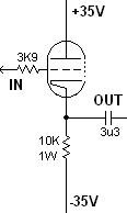
I have tried to pick out a bit of the Tube Buffered gainclone to make an output buffer for a CD-PRO2M. I want try it to see the difference in sound.
I was hoping someone would check to see if this is OK, or if I have left out any thing I'd need.
Thanks,
Gaz
I have tried to pick out a bit of the Tube Buffered gainclone to make an output buffer for a CD-PRO2M. I want try it to see the difference in sound.
I was hoping someone would check to see if this is OK, or if I have left out any thing I'd need.
Thanks,
Gaz
Attachments
Hi,
Not sure what you expect to hear from a cathode follower, probably just the sum of fingerprints of the components used but here goes:
As for the circuit, if you put a 50 to 100K gridleak resistor "en lieu" of the volpot it should work.
Plus add a bleeder resistor of roughly 100 to 470K behind the coupling cap too.
Cheers,")
I want try it to see the difference in sound.
Not sure what you expect to hear from a cathode follower, probably just the sum of fingerprints of the components used but here goes:
As for the circuit, if you put a 50 to 100K gridleak resistor "en lieu" of the volpot it should work.
Plus add a bleeder resistor of roughly 100 to 470K behind the coupling cap too.
Cheers,
Well, the buffer is supposed to give the Gainclone a hint of "Tube" sound. Since I've rarely heard tubes (in fact, only the buffered Gainclone - with a buzz) I'm not sure what Im listening for. However, I'd like to see what the impact is on the output of the CD Player.
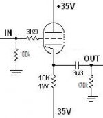
Is this revised schematic correct?
Kind Regards,
Gaz
Is this revised schematic correct?
Kind Regards,
Gaz
Attachments
Hi,
I doubt that's the main purpose but nevermind.
Yes.
You can safely reduce the 3K9 gridstopper (gatestopper in semi lingo) to 1K or lower.
Cheers,
Well, the buffer is supposed to give the Gainclone a hint of "Tube" sound.
I doubt that's the main purpose but nevermind.
Is this revised schematic correct?
Yes.
You can safely reduce the 3K9 gridstopper (gatestopper in semi lingo) to 1K or lower.
Cheers,
Or, if you don't mind a little higher voltage, this full implementation of Joe R's buffer:
http://www.diyaudio.com/forums/showthread.php?postid=546300#post546300
I think Steve Eddy showed a buffer in the same thread, with lower B+/- too.
sheldon
http://www.diyaudio.com/forums/showthread.php?postid=546300#post546300
I think Steve Eddy showed a buffer in the same thread, with lower B+/- too.
sheldon
Rarkov,
If you don't mind opinions, I would keep looking around for a better tube linestage to try out. The 6922 buffered GC is an elegant design in that you have 1 tube which handles 2 channels plus it runs off the same rails as the chip, so it is really a minimalist change. But I'm guessing you will have to add a +35V, -35V, and 6V for the heater to add it to your CDP....why? Seems like there are better choices if you look for them.
If you don't mind opinions, I would keep looking around for a better tube linestage to try out. The 6922 buffered GC is an elegant design in that you have 1 tube which handles 2 channels plus it runs off the same rails as the chip, so it is really a minimalist change. But I'm guessing you will have to add a +35V, -35V, and 6V for the heater to add it to your CDP....why? Seems like there are better choices if you look for them.
Hi,
Sorry to say so but 90% of what I read on that page is absolute nonsense.
Heater polarity, cascode stuff that has nothing, nothing whatsoever to do with the circuit shown.
Forget it.
BTW, why would anyone want to put a tube buffer behind a couple of stinkin' opamp buffers anyway?
If you want to work with valves then start on page one of the book, don't jump right in.
Sorry, had to get it off my chest,
Hi,
I have built Joe's VBIGC so many times now and it works great (for me at least), if I remember it right, Joe's reason for using a tube buffer is to isolate the feedback circuit of the GC amp from being affected by the position of the volume pot. Oh, and if you'll follow the schematic, the valve section has a separate trafo for psu and heater.
I was going to build that buffer in Sheldon's link, but a friend here told me to listen to an MF x10D tube buffer instead. Well I like it's sound, I think someone posted a similar schematic here but I can't find it even with local search. Or maybe it's somewhere else on the net.
As always, YMMV.
Jojo
I have built Joe's VBIGC so many times now and it works great (for me at least), if I remember it right, Joe's reason for using a tube buffer is to isolate the feedback circuit of the GC amp from being affected by the position of the volume pot. Oh, and if you'll follow the schematic, the valve section has a separate trafo for psu and heater.
I was going to build that buffer in Sheldon's link, but a friend here told me to listen to an MF x10D tube buffer instead. Well I like it's sound, I think someone posted a similar schematic here but I can't find it even with local search.
Or maybe it's somewhere else on the net.As always, YMMV.
Jojo
Hi,
Local search engine will dig up everything but that....
But indeed I recall that little buffer being discussed here maybe a year or two ago....
I should have that circuit in my archives somewhere too.
I'll stress once again the importance of understanding what you want to do here, if it's a certain sonic signature you're after and don't have a clue about what's inside you CDP then leave it as it is, it probably already has a buffered output. No need to add insult to injury...
If you just want a volctrl and a buffer to drive the IC running to the amp then a cicrcuit such as the 12BH7A I submitted here some time back would do the trick just fine.
Cheers,
Well I like it's sound, I think someone posted a similar schematic here but I can't find it even with local search.
Local search engine will dig up everything but that....
But indeed I recall that little buffer being discussed here maybe a year or two ago....
I should have that circuit in my archives somewhere too.
I'll stress once again the importance of understanding what you want to do here, if it's a certain sonic signature you're after and don't have a clue about what's inside you CDP then leave it as it is, it probably already has a buffered output. No need to add insult to injury...
If you just want a volctrl and a buffer to drive the IC running to the amp then a cicrcuit such as the 12BH7A I submitted here some time back would do the trick just fine.
Cheers,
Hi,
Thanks for all the replies. It serves no purpose other than to have a fiddle and see what the effect is (since I have the components spare).
I think I will try Sheldon's link. I have heard that the MF X-10 buffer adds something special to source equipment and I'm interested to try it.
Gaz
Thanks for all the replies. It serves no purpose other than to have a fiddle and see what the effect is (since I have the components spare).
I think I will try Sheldon's link. I have heard that the MF X-10 buffer adds something special to source equipment and I'm interested to try it.
Gaz
fdegrove said:Hi,
Local search engine will dig up everything but that....
Cheers,
Probably a copyright thingy.
Oh well... 
Hi There,
I used to have the MF X10D, indeed it did add some air and detail to an otherwise cheap CD player. used it for 7yrs before making my own valve preamp.
I made my own valve preamp based on Joes CC CV VB design. It has a similar effect to the X10D. Not a trivial matter to get the best out of this seemingly simple circuit. The power supply is the key.
Why not build a Valve ouput DAC. It uses the Valve in its optimum role as a current to voltage converter (DACs produce current), eliminates the opamps from the CD output. There are a few designs knocking about on the web.
Shoog
Hi,
I have a Perpetual Technologies P-1A / P-3A for the digital side so I can't justify replacing those yet...It is more interest to see what the effect is.
My plan is to make it switchable between the tube output and the CD Transport's output. I guess you could think of it as an A/B comparison....
Gaz
I have a Perpetual Technologies P-1A / P-3A for the digital side so I can't justify replacing those yet...It is more interest to see what the effect is.
My plan is to make it switchable between the tube output and the CD Transport's output. I guess you could think of it as an A/B comparison....
Gaz
opamps vs tubes
Hi,
I too used to think that opamps were good, but usually those 'awesome' distortion profiles have been gained thru masses of feedback, this makes things sound very flat when you compare them to tube circuits that use very little feedback. No matter how good you think opamps seem to sound, there's just no gong back once you compare with a good tube circuit. Tube circuits built properly can absolutley blow opamps away in every area. I would look for a good tube stage on the web, www.ultranalog.com has a few........
Frank is right there are far better ways to go about this.....
Thanks
Raja
Re: opamps vs tubes
Ultranalog has (sadly) been offline for a while. Some may have the valve output stages, named CD Enhancers saved on their computers, though.
Raj1 said:I would look for a good tube stage on the web, www.ultranalog.com has a few........
Ultranalog has (sadly) been offline for a while. Some may have the valve output stages, named CD Enhancers saved on their computers, though.
Some may have the valve output stages, named CD Enhancers saved on their computers, though.
Attachments
- Status
- This old topic is closed. If you want to reopen this topic, contact a moderator using the "Report Post" button.
- Home
- Amplifiers
- Tubes / Valves
- Tube Buffer for CD-PRO2M (6922)