2A3 Amp Layout Questions
Tenderland,
After doing this for a while, I have found that it usually makes sense to prototype your design on a board before building a chassis. This will allow you to test various components and play with your design before settling on a final configuration. Besides the obvious benefit of being able to listen and tweak your design, how to layout your final amp will be immediately apparent.
Good luck - ALBQ
http://mywebpages.comcast.net/gillespie147/2A3-Amp.html
Tenderland,
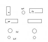
you might try orienting the choke's laminations 90º to the OPTs and see if you get lower noise/hum that way. Airgapped chokes inevitably spray leakage flux, but the relatively small AC voltage across them usually means this doesn't present as much of a problem. The problem here is that orienting it 90º to the OPTs places it in alignment with the power transformer - but this appears to be quite far away. Probably something that you will just have to try (unless you can mount the choke horizontally, of course). Moving the 2A3s closer to the edge may aid cooling, and the chassis tends to be more rigid at the edges. Do not forget to tightly twist heater wiring and push it into the edges of the (hopefully metal) chassis if you can.
ALBQ,
I know I'm doing a little nitpicking here, but I had a look at your amp and there is a mistake in the wording. Your amp is not valve regulated, and the 5U4 is not a valve regulator - it's a rectifier. Hence the amp has a valve rectified power supply, but is not valve regulated. Apart from that, a very nice amp. Those perforated anodes sure make the valves look nicer")
you might try orienting the choke's laminations 90º to the OPTs and see if you get lower noise/hum that way. Airgapped chokes inevitably spray leakage flux, but the relatively small AC voltage across them usually means this doesn't present as much of a problem. The problem here is that orienting it 90º to the OPTs places it in alignment with the power transformer - but this appears to be quite far away. Probably something that you will just have to try (unless you can mount the choke horizontally, of course). Moving the 2A3s closer to the edge may aid cooling, and the chassis tends to be more rigid at the edges. Do not forget to tightly twist heater wiring and push it into the edges of the (hopefully metal) chassis if you can.
ALBQ,
I know I'm doing a little nitpicking here, but I had a look at your amp and there is a mistake in the wording. Your amp is not valve regulated, and the 5U4 is not a valve regulator - it's a rectifier. Hence the amp has a valve rectified power supply, but is not valve regulated. Apart from that, a very nice amp. Those perforated anodes sure make the valves look nicer
Re: 2A3 Amp Layout Questions
Yep, and rotate the power tx and the choke till you find the position with minimum 50Hz at the output with the input shorted. Sometimes 90* isn't quite right. I don't generally like iron sitting on the top plate so it doesn't bother my aesthetic sense if components are at angles, so long as everything works perfectly.ALBQ said:Tenderland,
After doing this for a while, I have found that it usually makes sense to prototype your design on a board before building a chassis. This will allow you to test various components and play with your design before settling on a final configuration. Besides the obvious benefit of being able to listen and tweak your design, how to layout your final amp will be immediately apparent.
Good luck - ALBQ
http://mywebpages.comcast.net/gillespie147/2A3-Amp.html
2A3 Amp Layout
audiousername, tenderland,
Thanks, - as a note about the chassis. Was meant to be temporary so I could have the amp safely in my livingroom until I could make an exotic wood base (current base is Oak) - small children + pets + exposed 300V do not mix. That is why I did not trim all of the transformer leads. But alas, that was 2yrs ago. Still, building it on a test platform first (large soft pine board) meant that I could voice the amp how I wanted it and its dead quiet w/ 93db speakers. Other things I think are key to getting a quiet amp are 1) how the filament wiring is run - I do the same thing you do - twisted and close to chassis and 2) Grounding - a couple parts here a) I like to use a heavy gauge cooper wire to create a bus that everthing connect to that is ultimately tied to the chassis in a single location. This is also a good rule of thumb for safety and b) make sure that the grounding scheme never has a loop in it that might allow a signal path or potential difference
Cheers - ALBQ
2A3 Layour
Tenderland,
Can you be more specific what about what you want to know?
Bottom mounted iron on my amp are the big 2.5V filament transformers for each 2A3 and choke in the HV power supply
Iwould be interested on more info about iron not on top plate
Tenderland,
Can you be more specific what about what you want to know?
Bottom mounted iron on my amp are the big 2.5V filament transformers for each 2A3 and choke in the HV power supply
Hammond 302AX power transformer
Hi tenderland,
If you still haven't bought the power transformer, you may take a look at the Hammond 302AX which provides all the HV and filament supplies to the stereo 2A3 amp.
302AX
300-0-300 200mA
2.5V CT @ 2.5A
5V CT @ 3A
6.3V CT @ 6A
2.5V CT @ 2.5A
Then, you don't need a separate transformer for the two 2A3 filaments.
2A3 - Mount Iron
Tenderland,
Yes, I mounted the filament transformers and choke to the bottom of the top plate. Tried to do two things 1) keep all of the power supply transformers in the same general area - away from the 2A3's and 6SL7s but, close enough to where they were need to keep wire runs short and 2) reuse some of the mounting holes/screws to help keep the top plate clean - less stuff poking through it. I also left a couple places on the bottom free of paint so that I could make sure the top plate is electrically grounded.
Hope this helps -ALBQ
2A3 Layout
Tenderland,
I like to use soft pine or plywood for proto typing as I can mount everything using wood or sheet metal screws and screwdriver (see attached). I use scraps or small pieces of wood glued to the main board to hold transformers up so wiring is easy. Once I have the circuit working, no hum/noise, and voiced how I want it, I use the layout of the board as a starting point for determining the final layout. As this is a relatively time consuming process, builds in lots of time to think about the final chassis layout. For the final chassis I use a heavy gauge aluminum top plate and wood base - usually Oak. After drilling and cutting, I fine sand the top and bottom of the plate, mask where I want exposed metal on the bottom for grounding and spray paint it using rustoleum - usually bake at 100-150 in the oven with the door open for a little while to fully cure the paint. Then, let it cure fully for a day or two before mounting everything. I normally work with a folded towel on top of my workbench for final assembly to ensure I don't scratch anything.
Cheers - ALBQ
http://mywebpages.comcast.net/gillespie147/Images/6SN7-C4S-Top.jpg

- Status
- This old topic is closed. If you want to reopen this topic, contact a moderator using the "Report Post" button.
- Home
- Amplifiers
- Tubes / Valves
- 2a3 layout