Hi!
I find this simple OTL amp schematic, but I don't know should I trust it or not?
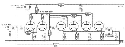
The author says that it is capable to drive a 15 Ohm speaker with 1-2 W ?!? Basicaly it is a headphone amp, but could be used also for sensitive speakers.The first tube could drive even more output tubes ( 10 ) and so could give more power.
Is it realy true?
Is the circuirt realy working?
Has somebody a very simple, but good OTL plan for an OTL beginer like me?
Tyimo
I find this simple OTL amp schematic, but I don't know should I trust it or not?
The author says that it is capable to drive a 15 Ohm speaker with 1-2 W ?!? Basicaly it is a headphone amp, but could be used also for sensitive speakers.The first tube could drive even more output tubes ( 10 ) and so could give more power.
Is it realy true?
Is the circuirt realy working?
Has somebody a very simple, but good OTL plan for an OTL beginer like me?
Tyimo
Attachments
Hi Tyimo,
To get 1W in 15 ohm you need to supply an RMS current of SQR(1/15) = 0.26A and a peak current of .36A and that is the mimimum cathode current in idle for the circuit in the attachement as it goes in class A, (in reality you need an even higher current to avoid unlinearities). There are 4 tubes so each tube need a curent of 90mA. To get 90mA cathode current at 0V at the grid you need a anode voltage of ~180V so the dissipation in each tube will be ~16W
The ECC88 is specified to max cathode current 25mA and max dissipation of 1.8W.
The cathode resistors value in the circuit look very high and can not be right, with 6.8k the cathode current will be very low, could it be that it should be 6.8ohm? also the anode resistor of 100ohm will limit the max current.
To answer your questions no, its not true, it cant give 1W even at 15ohm and it is not possible to build a 1W 15ohm amplifier with 4 ECC88 triodes, (they will probably melt). Also the circuit diagram is incorrect even for a headphone amp as some of the resistor values are wrong.
Regards Hans
Are you sure the ECC88 isn't just the driver tube?
It doesn`t help, with the anode and cathode resistor values shown it is impossible to get enough current to get any noticeable amount of power from this circuit.
Regards Hans
Hi Hans!
Thanks again, because last year You already answered me the same in e-mail!
I believed you, but I wanted to know is it posibble to modify-repair this circuit to working.
Do you know something very simple OTL to try? ca: 4-6 W on 16 Ohm?
(I didn't finished your great design OTL amp yet, because it is very hard to get the 6C33C tubes here)
Thanks again
Hi Tyimo,
The "only" problem with building an OTL is to make a circuit that can supply high enough current and doesn`t burn up. To make a class A OTL is much more difficult than class AB and that is why as far as I know there are only one low power class A OTL on the market and all others are class AB1 or even AB2.
An example: if we have a tube that can withstand a continous current of 0.5A we can build an class A OTL that can give 1W in 8 ohm, that is not very much, (the output power will be Ipk^2*Rl/2 or 0.5A^2*8/2 = 1W, in this circuit the peak current can never be higher than 0.5A)
If we use the same tubes in a class AB type amplifier we can assume that the tube withstand an average current of 0.5A but a higher instantanteous peak current and then the max output power will be higher. With 0.5A average current the RMS current is 1.1 higher or .55A and if we use 2 tubes the RMS current in the speaker can be allowed to be 2 times higher or 1.1A, this gives output power of 1.1^2*8 = 9.7W. The no signal current trough the tubes should be chosen at a reasonable value to minimise distortion and idle dissipation.
The simplest OTL circuit is probably the one that Philips had as example in their data sheet of EL86, it goes in class A and use only 2 tubes, see here http://www.tubetvr.com/otl.html I built this as my first OTL but with other tubes and got ~0.2W which was enough to get me interested in OTL`s. Using EL509 and 0.5A idle current this circuit can give ~1W with good reliability. For higher power class AB is the only way to go and then there are many circuits to chose from.
Regards Hans
A working schematic with ECC88s as power tubes....
.... but with an output transformer.
This amp was once published at the audiopages of Klaus Boehm ( website is down now ) with several other interesting projects. Klaus was the designer of a non oversampling TDA1541A DAC as well which inspired Thorsten to design the Adagio DAC. In other words, the published projects all worked and were thoroughly tested.
http://www.geocities.com/freespeedpro/1W-se.jpg
You must goto http://www.geocities.com/freespeedpro/ first and then change the address bar to http://www.geocities.com/freespeedpro/1W-se.jpg
http://www.diyaudio.com/forums/showthread/t-3273.html
In other words, the published projects all worked and were thoroughly tested.
Yes, the circuits look very similar except for that the one Tyimo showed is supposed to be OTL which the one you show is not. To get 1W from 4 ECC88 using an output transformer shouldn`t be any problem at all but quite impossible as OTL and normal speaker impedances.
The circuits are in fact very similar, so similar so I believe the non functioning OTL is based on the transformer coupled variant.
Regards Hans
tubetvr said:
The circuits are in fact very similar, so similar so I believe the non functioning OTL is based on the transformer coupled variant.
") My thoughts as well.
My thoughts as well.You are right of course about it being non-OTL. I guessed the emphasis was on a working power amp with ECC88 as power tube rather than it being OTL ( which it was not ). I edited my post according your comment.
> is it possible to modify-repair this circuit to working. Do you know something very simple OTL to try? ca: 4-6 W on 16 Ohm?
If there were a good way to drive speakers without costly transformers, the wise old men of the Golden Era would have done it.
Fact is: electrons do NOT want to cross a vacuum. And a speaker voice coil can't be wound with super-thin wire. Philips used thin wire for 800 ohm OTL amps, and even with the improved shellac of the late 1950s they had problems. The vacuum has to be much-much fatter than the wire. With more common speaker impedances, you need a BIG FAT VERY HOT vacuum.
The plan below will not work well as-shown but indicates the practical problems. You can do push-pull, a Futterman, but it is not simple nor easy to get happy. For "Simple" you end up with resistance-coupled Class A. Idle current has to exceed peak load current, about 1 Amp for your 6W in 16 ohm spec. No single tube will pass 1A continuously while negative-grid (and positive-grid adds complication). We need several big fat tubes. 6c33 is actually your best bet: ironic that you can't get them in former USSR-market areas. Type 6080 is a smaller US standard beast-triode.
Note that you will be sucking over 300 Watts from the wall to get up to 6W peak in the load. It is hardly transformerless: you have replaced 10VA-25VA of audio-iron with 50VA of power-iron. You also have an electrolytic cap in series with the output: different faults from a transformer, but hardly faultless.
OTL16
Hi,
Although OTL's are not simple it is not that difficult to get reasonable power with relatively uncomplicated circuits. 2 6C33C in single ended push-pull in class AB give 25W in 8ohm with high reliability, I have pushed out 25W in 8ohm from my own OTL during 24hours continous without any problem except that the amplifier got a bit hotter than usual. I agree that it is not a very efficient way to build an amplifier, (my 2 x 25W amp idle at ~400W dissipation) but it is not impossible to make it work well.
However to build an OTL in class A is something else, using 4 6c33c the idle current can maybe safely be up to 2A, (one 6C33C can idle at 550mA but this must be derated somewhat to allow for unequal curent sharing) but 2A idle can probably give up to 10W in 8 ohm at reasonable distortion but each 6c33C will then dissipate ~40W from the anode and the same from the heater so total dissipation will be at least 320W for one channel for the output tubes only.
BTW Both tubes.ru and GS tubes sell 6C33C for ~15 USD each
Regards Hans
Hi there......I
use a similiar circuit in my preamp with parallel sectioned ECC88 but into 3:1 stepdown to balanced 600 ohm o/p......the feedback from o/p into the input (in diag shown)will lower the input impedance.....In my case I don't use feedback so that that the preceeding audio stage can supply enough signal swing headroom without the stage loading introducing distortion. (there is no gain with cathode follower.)
rich
- Status
- This old topic is closed. If you want to reopen this topic, contact a moderator using the "Report Post" button.
- Home
- Amplifiers
- Tubes / Valves
- OTL ECC88 amp