Sheldon said:If I measure from B+ to the CT, that gives about 325v total, so that adds up, but still seems low given that my primary has 320v AC on each input leg to the rect. tube, under load.
Eh, don't sweat it. Could be anything, extra resistance in the transformer (did you enter it correctly in PSUD? Leakage inductance perhaps?), bogey tube, whatever.
Across the 170ohm, I get about -21v. When I channeled Mr. Ohm, he said that my total current draw is about 200ma. Where did those extra 50 or so ma come from? (remember, I have about 35ma for each of the output tubes and 4ma for the input tubes)
Hm, doublecheck output tube current, voltage and bias resistance? Ohm's law doesn't fail, the current's in there somewhere!
By grid leak, I assume you mean the 100k resistor from input to ground. Yup, that's there. I did measure voltage on the input grid with the nothing on the input and get about -400mv, so something's sucking electrons off that grid.
Yipe, sounds like grid leakage to me! Try a different 6SN7.
The plate is at about 45v and the cathode is about 250mv, so how can the grid be negative with nothing connected to it except a 100k resistor to ground?
The same way a thermionic diode creates current at zero terminal voltage (try it with a 50uA meter and a 6AL5!), the space charge around the cathode makes a virtual cathode phenomenon which effectively biases the cathode down a volt volt or so. If the surrounding electrodes are "ground potential", the cathode (or in this case, the grid, faulty with collected loose cathode material and heated by being so close to the actual cathode) natually becomes negative.
Open circuit grids often self-bias to -1 to -3V (regardless of plate voltage).
400mV across 100kohm comes to 4uA, spec is usually a tenth of that for grid current? Yeah, probably the tube...
I didn't actually measure the temp, but I'm guessing that it's about 70 degrees absolute. Might pass the 10 second test. But that leads to another question. Say I wanted to make a hybrid bridge, or even just ss. Can I open the tranny and will I find the individual ends of the CT so that I can parallel the sections, or will I have to dig deep?
Not recommended. The insulation in the transformer is placed assuming no voltage appears between the two ends which make the center tap.
Why bother with a FWB anyways, FWCT is 100% ideal - it's twice as efficient - the *only* reason it isn't done today is because the extra two solid state diodes are far cheaper than an extra winding on the transformer. In the old days, iron was cheaper than glass, so they opted for FWCT. (Not to mention the annoyance of floating two additional heater windings to complete a tube FWB.)
So using SS at all is probably a bad idea, since the supurlative efficiency will overvoltage your circuit (about 1.4 x RMS (300VAC in, 400VDC out) instead of the lame 1x (300VAC in, ~300VDC out) you are getting now). If you want to go this route anyway, you can tweak some resistor values, or even use some beefier output tubes, to account for the better power supply.
Tim
Sch3mat1c said:Eh, don't sweat it. Could be anything, extra resistance in the transformer (did you enter it correctly in PSUD? Leakage inductance perhaps?), bogey tube, whatever.
Tim
Yup, that was it. I measured the resistance of the secondary and entered that value (70ohm) instead of the default (33ohm). Gets me close to the measured value.
Sch3mat1c said:
Hm, doublecheck output tube current, voltage and bias resistance? Ohm's law doesn't fail, the current's in there somewhere!
Tim
Yeah, I goofed on that one too. Measured from the output of the neg. supply with load. When I measure across the 170ohm resistor, I get -24v, which gives me a total current of about 140ma.
Sch3mat1c said:
Yipe, sounds like grid leakage to me! Try a different 6SN7
the space charge around the cathode makes a virtual cathode phenomenon which effectively biases the cathode down a volt volt or so. If the surrounding electrodes are "ground potential", the cathode (or in this case, the grid, faulty with collected loose cathode material and heated by being so close to the actual cathode) natually becomes negative.
Open circuit grids often self-bias to -1 to -3V (regardless of plate voltage).
400mV across 100kohm comes to 4uA, spec is usually a tenth of that for grid current? Yeah, probably the tube...Tim
It's a 12BZ7 (not that that changes the idea). I framed the original question poorly. Just to make sure we're talking about the same thing: When I have nothing on the input, except the 100k grid leak, I measure negative 400ma on the grid, so I think we are talking the same thing. I've tried several tubes, all exactly the same, so I don't think it's the tube. I even tried some 5751's, same result. Where do I find specs. for grid current? Don't seem to be on common data sheets.
Sch3mat1c said:
Not recommended. The insulation in the transformer is placed assuming no voltage appears between the two ends which make the center tap.
Why bother with a FWB anyways, FWCT is 100% ideal - it's twice as efficient - the *only* reason it isn't done today is because the extra two solid state diodes are far cheaper than an extra winding on the transformer. In the old days, iron was cheaper than glass, so they opted for FWCT. (Not to mention the annoyance of floating two additional heater windings to complete a tube FWB.)
So using SS at all is probably a bad idea, since the supurlative efficiency will overvoltage your circuit (about 1.4 x RMS (300VAC in, 400VDC out) instead of the lame 1x (300VAC in, ~300VDC out) you are getting now). If you want to go this route anyway, you can tweak some resistor values, or even use some beefier output tubes, to account for the better power supply.
Tim
Well sounds like the best option would be to beef up the tranny if I want higher B+. They are not that expensive.
Thanks for the help. The only question remaining is the matter of the grid voltage on the input, or whether it matters at all. I think I'll play with resistors on the grounded grid to see where that gets me.
Thanks,
Sheldon
nanana said:hey sheldon,
congratulations on building your first tube amp...! (did i understand that right?) i hope you have enjoyed yrself? i built that amp in 1986 and i don't remember much about it other than it worked fine and i was into coltrane and ornette back then. oh yes, it was fisher 7591A outputs from a 400 series amp that came out of the garbage. you are absolutely correct at pointing out the mistake with the power trans center tap... it goes to the 170 ohm res. that is a back bias circuit which is just a cheapo neg. supply. the CRD2.0 needed the -30 to really nail the AC balance. i checked that on a scope until it worked right. it would be much less with a J310. i won't argue the direct coupling comments other than to say that i just don't agree... this is a very simple amp that works better than it has any right to. i will say the one caveat with that is that this is a DC coupled differential amp with a current sourced first stage. if you get that, then you understand why it works as well as it does. it is also a class A amp, with some headroom... there's not really enough swing or current in the driver to do much AB1. also, there were never enough 6CK4s to get a good match and i didn't want any fancy bias **** so i arranged the amp so that it wouldn't matter. i never had a matched pair of tubes and "DC balance", it isn't necessary except if you are desperate to maximize power output. it might mean a watt more or less in class A. not even 3dB more sound pressure in a 96dB per watt speaker at nominal listening level. the seperate cathode resistors on the outputs allow for different tube currents. all it means is that the clipping point is determined by the tube that goes first... the forced AC balance from the output tranny straightens things out. the 12BZ7 is OK. a 12AX7 is just as good. i have no preference. i did it first with a 12AX7 and got bored... they both worked. i probably had to adjust the dropping res a bit... you can change it if you like, obviously! it sounds to me that you have really taken this project to heart and have learned something from it?! i have never used a modeling program in my life and it would seem that you have used yours to get a better understanding of what is doing what... i really take my hat off to you. as for your questions, i don't remember where or what the power trans i used came from or was... the line voltage here in NYC is generally on the high side (120+) and it also doesn't matter that much unless you need more watts. i don't know anything about the hammond you have... is the heater winding rated enough for the 6CK4s + the driver tube. i seem to remember they draw a lot of current? did you make a DC supply for that? that would increase the current draw by 1 and half times and perhaps pull down the mains B+ by heating the tranny. i don't think i can help much without more info... but perhaps you should just listen to some music for awhile? you can optimize it later...
jc
Thanks, JC. Yes, it is my first tube project. Recently built a couple of chip amps, and years ago, a DynaKit transistor amp. I have a few J310's left over from the chip amp projects (used as current sources for a regulated supply and for an input buffer). I may try them with a variable resistor so I can fiddle with the current, if I want to try different input tubes.
In my reply to Schematic, I think I have got the power supply issues figured out. The heaters (AC) are ok, in fact I had to drop the voltage a bit with in-line resistors. By the way, any advantage in going DC on the heaters here (lower hum for very high eff. speakers?). As I understand it, the differential design should give pretty good PSRR already.
So the only remaining question is that of the voltage on the input grid, and what to do with that. I get about minus 400mv on the input grid when it's not shorted to ground. Schematic offered some discussion on that, but I'll ask you too. That gives me an imbalance of 80/50volts on the respective output tubes. If I understand your reply, I think you are saying not to worry about it. I would think that it wouldn't hurt to have both input and output somewhat balanced. Would it create any problem to place a resistor on the grounded side to get them closer?
Sheldon
Sheldon said:I measure negative 400ma on the grid,
Sheldon
Oops, I meant 400mv.
Sheldon said:Yup, that was it. I measured the resistance of the secondary and entered that value (70ohm) instead of the default (33ohm). Gets me close to the measured value.
Yeah, I goofed on that one too. Measured from the output of the neg. supply with load. When I measure across the 170ohm resistor, I get -24v, which gives me a total current of about 140ma.
Ah, very well then. The world works

It's a 12BZ7 (not that that changes the idea).
D'oh, how'd that get in there!

I framed the original question poorly. Just to make sure we're talking about the same thing: When I have nothing on the input, except the 100k grid leak, I measure negative 400mV on the grid, so I think we are talking the same thing. I've tried several tubes, all exactly the same, so I don't think it's the tube. I even tried some 5751's, same result. Where do I find specs. for grid current? Don't seem to be on common data sheets.
Hm, possible ground loop offset (same idea as the power supply/bias resistor but smaller and unintentional)? Lemme check... average sheets don't have a grid current spec but mil types do. I have a printout for 6922 (6DJ8 equiv.) here which says... MIL-E-1 Ref. 4.10.6.1 Grid Current: 0 (minimum) to -0.2 (maximum) microamperes (after heating no less than five minutes at a specified DC condition). A mini type (mu = 70) shows 1uA max.
Given that all your tubes give the same offset, I'd suspect you might be reading it wrong. Hm, maybe contact resistance in the sockets?
Well sounds like the best option would be to beef up the tranny if I want higher B+. They are not that expensive.
Well, a transformer and tube diode are about equally matched, and "not that expensive" depends on the scale of your checkbook...
If you re-read my paragraph (and sorry for phrasing it as I did), you'll note you get more voltage with all SS than with a tube diode wrench in the works, I simply don't recommend it right now until you've swapped out the appropriate resistors to make sure it doesn't have a heat stroke.

Tim
Sch3mat1c said:Hm, possible ground loop offset (same idea as the power supply/bias resistor but smaller and unintentional)? Lemme check... average sheets don't have a grid current spec but mil types do. I have a printout for 6922 (6DJ8 equiv.) here which says... MIL-E-1 Ref. 4.10.6.1 Grid Current: 0 (minimum) to -0.2 (maximum) microamperes (after heating no less than five minutes at a specified DC condition). A mini type (mu = 70) shows 1uA max.
Given that all your tubes give the same offset, I'd suspect you might be reading it wrong. Hm, maybe contact resistance in the sockets?
Tim
I think I get everything else. But this one has me stumped. I still get -400mv, so with a resistor of 100k that's 4uA. I don't see any sign of bad grounds (0volts everywhere), but I'll look very closely. Whatever I've got going wrong, it's systematic, as I get the exact same results on each channel. So I don't think it's a bad component.
Oh, on the transformer, I was asking about opening it up only because I thought that a hybrid bridge might just get me the extra volts I need. I.e., midway between the ss bridge and tube fw. Or is that notion all wet.
thanks,
sheldon
jlsem said:
???????????
At least 6 different tubes give the same result. No, I don't think it's a faulty component.
Wiring issue - perhaps, but I can't find it. If I did something wrong, I did it on both sides of the stereo amp. I've checked and rechecked. I'll keep at it until I figure this out.
Sheldon
Sheldon said:I think I get everything else. But this one has me stumped. I still get -400mv, so with a resistor of 100k that's 4uA. I don't see any sign of bad grounds (0volts everywhere), but I'll look very closely. Whatever I've got going wrong, it's systematic, as I get the exact same results on each channel. So I don't think it's a bad component.
Hmm weird. You're measuring right across the resistor's leads, right?
Oh, on the transformer, I was asking about opening it up only because I thought that a hybrid bridge might just get me the extra volts I need. I.e., midway between the ss bridge and tube fw. Or is that notion all wet.
Nah, if you work through it you'll see you get the regular tube voltage drop, plus the SS diode drop (negligible of course). That's why FWB is the worst of any rectifier.
Tim
Sch3mat1c said:
Hmm weird. You're measuring right across the resistor's leads, right?Tim
Yup. In the meantime, browsing the other threads on the tube fourm, I came across the one referring to conversion of 6.3v filaments to DC. You had suggested raising the filament supply above the highest cathode voltage. I'm gonna do it because it sounds like a good idea anyway, but I wonder if that might bear on this this issue too.
Sch3mat1c said:Nah, if you work through it you'll see you get the regular tube voltage drop, plus the SS diode drop (negligible of course). That's why FWB is the worst of any rectifier.
Tim
Makes sense. The resistance is in series. I guess that technique would be useful if you wanted the soft start of a tube and maybe more gradual diode shut-off characteristics?
Sheldon
Sheldon said:In the meantime, browsing the other threads on the tube fourm, I came across the one referring to conversion of 6.3v filaments to DC. You had suggested raising the filament supply above the highest cathode voltage. I'm gonna do it because it sounds like a good idea anyway, but I wonder if that might bear on this this issue too.Sheldon
Well, probably not. I raised the filament supply to about 95volts. The 6CK4 cathode tops out at about 90v. The 12BZ7's are close to ground. No change at all on the grid voltage of the BZ7's. I don't think I've done anything grossly out of wack. The amp actually sounds pretty nice, based on limited listening. I get about 2ma of hum, which ain't too bad for starters, especially considering the minimally filtered supplies. The voltages across the output transformer primaries are within a volt, with the input shorted or open, so that shouldn't create a problem. But dadgummit, this is bugging me. I'm not quitting until I understand the mechanism.
Sheldon
Ok, I think I've got it.
If you look at the bottom of this page:
http://w3.mit.edu/cheever/www/new.html , it appears that the expected grid current is indeed about 5ua (remember, the 12BZ7 section is like a paralleled 12AX7). My plate voltage is about 45v and the current is about 1ma per section, so I'm right in the ballpark. With the input open, I calculated a current imbalance of 0.13ma. For a voltage imbalance of 400ma on the grid, and a current imbalance of +-0.13ma, by measuring the voltage drop across the respective plate resistors. I calculated that I would need a 3k resistor on the grounded cathode to bring the grounded grid into balance. Sure enough, adding about 3k did the trick. Everything balanced. Of course, when the input is now shorted, the imbalance goes the other way. No problem if I have a constant impedence on the source, cause I can compensate for it. But a changing impedence would not be so good.
What to do? Well, I can raise the plate voltage. The schematic call for about 80v, and I'm at about 45 now. If I read that graph right, getting the plate voltage up to 80 should drop the grid current by a factor of 10. I could also reduce the value of the grid leak resistor, as long as my source don't mind. Or, both. Or, I could add a buffer, and not worry about it much. Is this what they mean when they say that audio design is all about making the right trade-offs?
Please don't tell me I'm way off, unless you can tell me where to go (ah, careful there). Of course, I'm drinking a glass of wine while I write this, so who knows?
Sheldon
Sch3mat1c said:Coupling cap to isolate grid from DC potential of signal source.
Tim
That's certainly an option. I was waiting for that one.
Ok, hows about this for an option: I modeled up a ss full wave rectifier in PSUD (RCLC, 10ohm, 47uf, 1.5h, 150uf, with transformer R of 75, and inductor R of 52). Gives me a nice 365volts B+, with little ripple, and I have the parts. Then, I have the octal slot for the rect. tube open. What dual triode would you use for a buffer in that slot, and what configuration? I know that there are plenty of 9pin tubes, but I don't want to mess with the chassis if I don't have to.
Substituting a 5AR4 for the 5Uu4G also gets me pretty close to the voltage I want. I'll probably try that first, because it's easier.
Sheldon
"I reject your reality and substitute my own!" Don't we all?
Sheldon said:. The schematic calls for about 80v, and I'm at about 45 now. If I read that graph right, getting the plate voltage up to 80 should drop the grid current by a factor of 10. Sheldon
Confirmed by test. If I raise the plate voltage of the 6BZ7 to 80, I get a small deviation on the input grid and a corresponding small change of only a couple of volts on the 6CK4 cathodes. If I go to 100volts, the change is nil.
So the general lesson might be that, in these high gain tubes, lowering plate voltage (and/or increasing current) beyond a certain point gives a rapid rise in grid current.
Sheldon
Makes sense. 45V is absurdly low plate voltage...
Increasing it would keep the electrons flying straight, same as a screen grid pulling less current... on the other hand, that's a positive, not negative current.....
FWIW, the 10 ohms in your rectifier doesn't do much since it's in series with the capacitor's ESR and the transformer's DCR, the latter being more significant.
Tim
Sch3mat1c said:Makes sense. 45V is absurdly low plate voltage...
Increasing it would keep the electrons flying straight, same as a screen grid pulling less current... on the other hand, that's a positive, not negative current.....
FWIW, the 10 ohms in your rectifier doesn't do much since it's in series with the capacitor's ESR and the transformer's DCR, the latter being more significant.
Tim
True, about the plate voltage. The schematic infers a plate voltage of about 80v. One thing about the power supply the way it's drawn up is that it's all completely interdependent. So, I'll have to adjust some of the dropping resistor values. Actually a B+ of 365v at the plate of the 6ck4 would put the tube right at the max for power with 80volts on the grid, so probably best to back that down a bit anyway.
As for the 10ohm resistor, I just played with the values until I got a nice smooth leading edge on the output voltage curve. Real life would vary from that somewhat, I suppose.
Thanks for all the help.
Sheldon
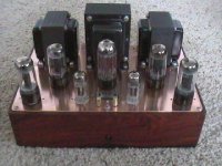
Completed Amp
It works and sounds very nice. I haven't been able to crank up the system as my main speakers are only about 87db eff. But at moderate levels, very nice. Very well behaved, as in no thumps or noise at start-up and residual hum of less than 1.5ma (can hear 60hz within 6 inches of speaker only).
Note that I'm using GZ34S (JJ) instead of 5U4GB, to get the voltage up. If it doesn't like the large input cap and dies early, I can go up one size in the power transformer (current unit seems maxed out, gets pretty warm but is within rating of 200ma). Or I could do what Tim suggested way back and use caps between stages. Then I could use lower voltage, as the output tubes cathodes could be only around 25 volts (less heat in the cathode resistors too). Could also up plate voltage on the input tubes. But no problem so far with the rec. tube and it gives a nice slow turn on (about 30 sec.). The heater voltages were a bit high, even before I switched to the GZ34, so I added series resistors to get to 5V and 6.3.
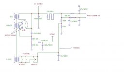
Note the trimpot on the CCS. I can go from about 1ma to about 10 or so, if I want to change input tubes (say 12AX7 or 5751). They are set at the spec.'d 2ma now. The 1k resistor is just to make it easy to measure the current setting.
I didn't show the balance meter in the schematic, but it's done similar to what is shown here: http://www.wdehaan.demon.nl/mono/mono/el84dc.html
The only real difference is that I use only one meter for both channels and used a DPDT switch to go back and forth. With the switch left, I read and adjust the left channel tubes, and visa versa. In the middle position the meter measures the + tube of the left channel with the - tube of the right channel, so I can get a good look at the entire balance. So far, they don't drift much day to day - a couple of volts max. Don't yet know long term, but JC didn't think it was an issue anyway.
I added a little 12v fan and power supply to keep things cool. Very quiet, as I run it at 7VDC.
Here is the amp schematic, with actual voltages:
It works and sounds very nice. I haven't been able to crank up the system as my main speakers are only about 87db eff. But at moderate levels, very nice. Very well behaved, as in no thumps or noise at start-up and residual hum of less than 1.5ma (can hear 60hz within 6 inches of speaker only).
Note that I'm using GZ34S (JJ) instead of 5U4GB, to get the voltage up. If it doesn't like the large input cap and dies early, I can go up one size in the power transformer (current unit seems maxed out, gets pretty warm but is within rating of 200ma). Or I could do what Tim suggested way back and use caps between stages. Then I could use lower voltage, as the output tubes cathodes could be only around 25 volts (less heat in the cathode resistors too). Could also up plate voltage on the input tubes. But no problem so far with the rec. tube and it gives a nice slow turn on (about 30 sec.). The heater voltages were a bit high, even before I switched to the GZ34, so I added series resistors to get to 5V and 6.3.
Note the trimpot on the CCS. I can go from about 1ma to about 10 or so, if I want to change input tubes (say 12AX7 or 5751). They are set at the spec.'d 2ma now. The 1k resistor is just to make it easy to measure the current setting.
I didn't show the balance meter in the schematic, but it's done similar to what is shown here: http://www.wdehaan.demon.nl/mono/mono/el84dc.html
The only real difference is that I use only one meter for both channels and used a DPDT switch to go back and forth. With the switch left, I read and adjust the left channel tubes, and visa versa. In the middle position the meter measures the + tube of the left channel with the - tube of the right channel, so I can get a good look at the entire balance. So far, they don't drift much day to day - a couple of volts max. Don't yet know long term, but JC didn't think it was an issue anyway.
I added a little 12v fan and power supply to keep things cool. Very quiet, as I run it at 7VDC.
Here is the amp schematic, with actual voltages:
Attachments
- Status
- This old topic is closed. If you want to reopen this topic, contact a moderator using the "Report Post" button.
- Home
- Amplifiers
- Tubes / Valves
- 6ck4 pp amp