I'll be powering the filments for a 6N1P and a KT88 from the 6.3V secondary. Neither tube has a CT connection for the heater but my PTX does have a CT for the 6.3V secondary.
So my thought was to simply cap the CT and not connect it to anything. However after searching here I see that some people recommend connecting the filament CT to chassis ground (safety ground, earth ground, green wire from the mains cord).
My current design has the CT from the HV secondary forming the power ground. The ground side of the filtering caps will be connected to this ground. My signal side has a separate single ground point. I will connect the earth ground to the chassis. I then plan to use a heavy gauge solid core wire (12AWG) to connect the signal ground to chassis ground and to connect the power ground to chassis ground.
What do more experienced builders recommend?
A- cap the CT and connect it to nothing
B- connect the CT directly to chassis ground
C- connect the CT to power ground
Thanks!
Hi,
Only those tubes that offer the possibility of heating from either a 6.3V or 12.6V supply have a center tap.
That will work.
That's how it should be done to lower hum levels.
Either B or C depending on the rest of the grounding set up.
Cheers,")
Neither tube has a CT connection for the heater but my PTX does have a CT for the 6.3V secondary.
Only those tubes that offer the possibility of heating from either a 6.3V or 12.6V supply have a center tap.
A- cap the CT and connect it to nothing
That will work.
B- connect the CT directly to chassis ground
That's how it should be done to lower hum levels.
C- connect the CT to power ground
Either B or C depending on the rest of the grounding set up.
Cheers,
fdegrove said:Hi,
...Either B or C depending on the rest of the grounding set up.
Cheers,
Frank,
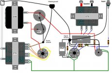
I've attached a drawing of my grounding scheme. Note that it isn't totally accurate in the placement and orientation of the components but it does show how I intend to ground things. Note it also doesn't show the 6.3V CT.
On the left is the "power ground" with the CT of the high-voltage secondary and the grounded side of the filter caps. This ground is not connected to the chassis at this point.
On the right is the "signal ground" where all the grounds from the tubes are connected along with the ground of the input jack. This ground is not connected to the chassis at this point.
At top is the chassis ground where the mains ground wire will connect to the chassis. Both the power ground and signal ground will also be connected there.
Although not shown on this drawing there is a 6.3V CT and I think it might be best to connect it directly to the chassis ground point rather than the power ground.
I hope this will work to reduce chances of ground loops between difference in potential from the signal ground point and the power ground point could cause current flow.
Attachments
Hi Sherman,
I would connect it to the power ground...
Since I build wooden chassis...I have only one ground..signal/power ground it's all the same...I can't hear hum when I push my head near the speaker cone. 90db efficient.
You will get massive hum if you don't use your filament CT
What program do you use for tubepad? I find that Photoshop does not really lend itself to drawing with tupepad.
Regards,
Bas
Bas:
I would get a 100 ohm 5 watt wirewound pot and hook it across the filament winding and either ground the center ( rotor ) or hook it up to the cathodes of the output tubes. This way you can use either hook up and rotate the pot for minimum hum in the output.
This does work, check any RCA tube manual.
Edward Lipman
Bas Horneman said:...What program do you use for tubepad? I find that Photoshop does not really lend itself to drawing with tupepad.
Regards,
Bas
Bas,
I just use Windows Paint. I actually haven't tried it with Photoshop. I haven't done anything more complicated that the drawing I posted here but Paint seems to be OK for that type of thing.
eds65gto said:...100 ohm 5 watt wirewound pot and hook it across the filament winding and either ground the center ( rotor ) or hook it up to the cathodes of the output tubes....
Edward Lipman
Bas Horneman said:Hi Edward,
...But do you reckon that would be necessary on IDH tubes? I dunno...
Regards,
Bas
I don't think it would make a difference with an indirectly heated tube. Necessary on a 300B but I don't think it would do anything with a KT88. However I only have one toe past the newbie line so I'm definitely no expert.
If it would help I still have time to work it in to the design!
Bas Horneman said:Hi Sherman,
...Since I build wooden chassis...I have only one ground..signal/power ground it's all the same...I can't hear hum when I push my head near the speaker cone. 90db efficient.
...
Regards,
Bas
Bas,
Forgot to mention, this will also have a wooden chassis. I originally planned to make it from Corian but for now I'm going with wood. The top plate is 1/8" aluminum.
However there can still be a difference in potential from one side of the aluminum plate to the other. That's why I thought I would not connect the power and signal grounds to the chassis where they are but instead use a "ground bus" and connect them to a central "chassis ground".
It is nice to know that your amp doesn't have a problem with hum with only one ground point. It gives me hope this will work. I've got a bit of money and time invested to get to this point and I really want it to work.
pedroskova said:Hi Sherman,
Hope I'm reading everything properly...but I would be inclined to take that last 220uF cap to power ground, and place my signal star ground at the input ground and take it from there to power ground...if that makes any sense.
Oops! I see I've got the caps connected to the wrong places. The 100uF should be connected to the 6N1P and the 220uF should be connected to the KT88!
So I assume you are saying that the bypass cap on the output tube should be connected to power ground, correct?
And you are recommending I use the input jack ground as the signal ground point? I had actually thought about doing that but set it up this way because I've been moving the input jack around. Ideally it should be next to the 6N1P but I don't like the way it looks to have the inputs up front. I may change my mind before this is done!
I hope to start drilling the top plates in the next few days.
Here is my latest little project on a wooden "plate" ...John Broskie's Aikido...
more pics
http://basenjes.de/tubes/images/aikido/index.html
a Little upside down 9pin tube with a 2mm copper wire wrapped all around it...is my star earth...
...John Broskie's Aikido...An externally hosted image should be here but it was not working when we last tested it.
more pics
http://basenjes.de/tubes/images/aikido/index.html
a Little upside down 9pin tube with a 2mm copper wire wrapped all around it...is my star earth...
Bas Horneman said:Here is my latest little project on a wooden "plate"
more pics
http://basenjes.de/tubes/images/aikido/index.html
a Little upside down 9pin tube with a 2mm copper wire wrapped all around it...is my star earth...
That is a very nice looking amp! When you said you used wood cabinets I didn't realize you meant the entire thing, including the top plate!
Very impressive work.Beautiful pre. How do you like the Aikido? I'm thinking of doing one myself and have sim'med the heck (the most extreme expletive the filters allow apparently) out of the circuit. There are a couple of very trivial modifications which would seem to gain +30 dB extra PS rejection if you're interested.
BTW, double check the circuit on your page. As drawn it has near infinite input audio rejection.
BTW, double check the circuit on your page. As drawn it has near infinite input audio rejection.
I started building without breadboarding it first....Beautiful pre. How do you like the Aikido?
the wooden top costs about 1 dollar. And I can always chop and change when it is in the box.Thanks will check to see if I can spot the error..it was very late when I drew it ;-) [edit] Aha..I should connect the anode of the bottom 12sn7 to the voltage divider.As drawn it has near infinite input audio rejection
Very interested...thanks. Usually I like to keep it simple..very simple...but I wanted to try something that is out of the ordinary for me....There are a couple of very trivial modifications which would seem to gain +30 dB extra PS rejection if you're interested.
Maybe an interesting anecdote...I haven't even tried to understand the circuit yet...I usually just build something and listen...If it works well...I'll invest my time in trying to understand how it works
Will report...you might have to have a lot of patience. I'm going on holiday soon for 3 weeks.It will very interesting to hear how you like its sonics...
But I will try to get it up and running before this friday...
I actually expect a problem with my power transformer...I wanted to do this whole thing without boutique stuff..and frugally..
So I took 2 9volts transformers and fitted them back to back..I've never done this before...and with 4 tubes the current draw should be quite hefty...if it proves to much ...I'll just draw from my current preamp...which has plenty current!
Cheers,
Bas
- Status
- This old topic is closed. If you want to reopen this topic, contact a moderator using the "Report Post" button.
- Home
- Amplifiers
- Tubes / Valves
- Grounding Filament CT?