Hi,
Errrrrrrrrrrr.....That there isn't much left to call it SRPP?
Cheers,")
what do you think about this design?
Errrrrrrrrrrr.....That there isn't much left to call it SRPP?
Cheers,
Yvesm said:How many sections would be necessary to drive an 8 ohms load at, uuuh, 1 Watt ?
Just one, if you have a 10k 1W OPT.
Tim
thanks for your replies guys!
..SRPP...well maybe i should call the circuit SEPP instead?
-> fscarpa58
do you really 100uf at the output is sufficient, i'd rather raise the value to 680uF than lower it to 100uF, as far as i recall the higher capacitance the lower will the -3dB point be..?!
(though not extremely low..)
->geek
and what is your opinion about the sound of circuits like this? could i get away with a total of only three triodes?
->Sch3mat1c
well... my thought was to do something different from the usual cathodefollower..
-is it realistic to think that the output would swing about 1,5-2V p-p?
-my intention is to try this kind of topology and, of course, later on cannabilise
it for parts (like most of my projects..) if this project doesn't perform well enough.. *lol*
Mr. Triatic said:->geek
and what is your opinion about the sound of circuits like this? could i get away with a total of only three triodes?
My opinion is....I never want to hear sound any other way again
You could if you have sensitive enough headphones. Build the circuit on a breadboard and give it a try. Is the sound to your liking? Is the volume enough? If yes, you have a winner
If the sound isn't OK, try different tubes (Paralleled 6N1P are pretty good too
). If the sound is OK, but not the volume, use more tubes.Hi,
Neither.
BTW, the top triodes aren't biased properly either, PSRR is virtually nonexistant too.
May I suggest a SRPP stage followed by a WCF a la John Broskie's Aikido circuit?
With a decent PS and a volume control on the input it could double as a superb little preamp as well.
It would do nicely with all the gain AND drive for any headphone, even the lowest input impedance and silliest interconnect capacitance could be driven from that, hands down.
Cheers,
..SRPP...well maybe i should call the circuit SEPP instead?
Neither.
BTW, the top triodes aren't biased properly either, PSRR is virtually nonexistant too.
May I suggest a SRPP stage followed by a WCF a la John Broskie's Aikido circuit?
With a decent PS and a volume control on the input it could double as a superb little preamp as well.
It would do nicely with all the gain AND drive for any headphone, even the lowest input impedance and silliest interconnect capacitance could be driven from that, hands down.
Cheers,
Mr. Triatic,
Before attempting an SE amp to drive low-imp. headphones, I think you owe it to yourself to read this article, which also has pretty elaborate design examples:
http://www.tubecad.com/articles_2001/Inv_Dist_Cancellation/index.html
And here it is in PDF form:
http://www.tubecad.com/articles_2001/Inv_Dist_Cancellation/CompInvDisAmp.pdf
(Pages 9-12 are the most relevant ones.)
Even if you pass on the inv. dist. compensation, this will give you an idea of what you need in terms of current, no. of tubes, etc., for a successful design (IMO).
BTW, the SE design, using 5687s or 6N30Ps, is on my short list of what to do next! And note that it doubles as a line stage...
Best luck (whatever you come up with),
hi
The question is different. It is the 100u cap at the catode that
in isufficient. It is mandatory to rise its value. My solution is
at no cost and, yes, 100u at the output are sufficient but you
may increase this value as you feel. But, again, a value of
100u at the output and 1000u as bypass is also better.
So, the important thing is to rise the bypass cap.
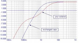
Sure, but do not forget the bypass cap. If it is not enough large
at low freq. there will be a feedback with lower gain.
In fact, look at the following pic.
at 1.5V p-p you'll have about 2.5% THD at 2V 5.5%
but I have used ECC88 curves rather than E88CC
http://www.mif.pg.gda.pl/homepages/frank/sheets/030/e/ECC88.pdf
bye
Federico
do you really 100uf at the output is sufficient, i'd rather raise the value to 680uF than ...
The question is different. It is the 100u cap at the catode that
in isufficient. It is mandatory to rise its value. My solution is
at no cost and, yes, 100u at the output are sufficient but you
may increase this value as you feel. But, again, a value of
100u at the output and 1000u as bypass is also better.
So, the important thing is to rise the bypass cap.
as far as i recall the higher capacitance the lower will the -3dB point be..?!
Sure, but do not forget the bypass cap. If it is not enough large
at low freq. there will be a feedback with lower gain.
In fact, look at the following pic.
is it realistic to think that the output would swing about 1,5-2V p-p?
at 1.5V p-p you'll have about 2.5% THD at 2V 5.5%
but I have used ECC88 curves rather than E88CC
http://www.mif.pg.gda.pl/homepages/frank/sheets/030/e/ECC88.pdf
bye
Federico
Attachments
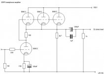
Here's a simple design - using ECC88's - for driving 300 Ohms or higher headphones:
http://gyraf.dk/tmp/Tube_headphoneamp.pdf
Has schemo and PCB layout..
Jakob E.
http://gyraf.dk/tmp/Tube_headphoneamp.pdf
Has schemo and PCB layout..
Jakob E.
- Status
- This old topic is closed. If you want to reopen this topic, contact a moderator using the "Report Post" button.
- Home
- Amplifiers
- Tubes / Valves
- SRPP headphoneamp with E88CC