I have purchased and completed the $139 tube amplifier kit by S-5 Electronics.
The amp was purchased from S-5 Electronics. The folks there are very friendly and helpfull and I recommend them. The kit was well packaged and arrived intact. Canadian duites, GST and fees was exactly $20CDN.
I have posted photos of my finished amp in the photo section:
http://www.diyaudio.com/forums/showthread.php?postid=541315#post541315
http://www.diyaudio.com/forums/showthread.php?postid=541318#post541318
Fitting the kit into an enclosure was much tougher than I had originally imagined. However, I think that it turned out rather nice. The front controls are a power switch, input selector and volume control. On the back are the speaker outs, RCA inputs, fuse and power cord.
The kit has been reviewed by AudioXpress, http://www.audioxpress.com/reviews/media/1102hansen2145.pdf
Since that review, it is important to note that changes have been made to the kit. Most impotantly, the tube sockets have been upgraded to ceramic to address the scortched socket problem. In addition, the circuit has been modified (addition of two capacitors) to reduce noise and hum.
I plan to listen to the amp more critically, but have the following initial impressions to share:
The amp is quiet and the transformers do not hum as others have reported.
Based on limited listening, the performance seems good and is a clear improvment over my mass produced SS amps (i.e. Sony etc.).
The power is only 8 watts per channel, however, 8 watts is much louder than I expected. It is loud enough on a pair of ~91dB speakers to make conversation impossible and get me evicted from my apartment.
As reported by others, the tubes run very hot, so do take that into consideration when fitting the kit into an enclosure. The power transformer also gets hot. Any comments as to why the transformer is that hot?
There is no safety bleeder on the power supply. However, keeping the speakers connected after power down seems to drain the capacitors sufficiently.
I have some tube dampers I want to try out. I am a little concerned that the tubes may be too hot.
I also have some polypropelyne caps that I will try in place of the metalized polyester input coupling caps.
I will also likey try the mods from http://www.siteswithstyle.com/VoltSecond/K-12M_AMP/K-12M_Push_Pull.html
I will post my results.
Regards,
Gio.
gmilitano said:It is loud enough on a pair of ~91dB speakers to make conversation impossible and get me evicted from my apartment.
LOL
 But I hope that was a joke...
gmilitano said:As reported by others, the tubes run very hot, so do take that into consideration when fitting the kit into an enclosure. The power transformer also gets hot. Any comments as to why the transformer is that hot?
The power transformer may run a little hot because it may not be sufficiently large enough (or not sufficiently overdone
). You'll probably have to live with it unless you replace it with something larger. Another problem that people sometimes run into is putting the valves too close to the transformer, heating it. It doesn't look like that though from the pictures (a little hard to tell though)Anyway, how hot is it? So hot you can't hold your hand against it?
gmilitano said:There is no safety bleeder on the power supply. However, keeping the speakers connected after power down seems to drain the capacitors sufficiently.
This is a transformer-coupled amplifier, and since the OPT can't pass DC, the speaker wouldn't be able to act as a bleeder. The B+ probably goes down because the valves remain conducting for a little while after the power is off (they can conduct as long as the cathode is hot), or through leakage in the B+ caps.Anyway, congratulations is in order. The more valve amps out there the better!
audiousername said:LOL
Like, Canadian made apartment, eh? We put R31 in the outside walls and nothing from apartment to apartment
Anyway, congratulations is in order. The more valve amps out there the better!
Agreed, congrats!
Gio, I had a look over the link you posted about mods to the amp, and I must say, it looks quite well thought out. I doubt you would go wrong with following those modifications.
It said at the end of the site about adding a bleeder to the supply. Well how about this idea... using the unused contacts of a DPDT power switch to switch in the bleeders only when the power is turned off. It would reduce the additional strain on the power supply caused by the bleeder current (I admit this may be negligible), but more importantly, will eliminate the production of heat in the bleeder when the amp is on. It seems that this amp is too hot already
Muhahahaha Australian apartments (well mine anyway ) have 13mm (1/2") plasterboard, something like a 50mm (2") airgap filled with fibreglass insulation, 150mm (6") or so of concrete blocks - and the same plasterboard and insulation on the other side. So the whole wall is like 300mm (12") thick, and caulked all around for fireproofing! To top it all off all the windows are double glazed and sealed, along with the gaps around the doors. So as long as the music stays above 100Hz and I'm not trying to destroy my hearing it's
  for the neighbours. But darn, those bass notes are pervasive
Edit: Whoops, I forgot to attach the file. Doing a lot of that nowadays As you can see, using the generally unused switch contacts was not my idea.
It said at the end of the site about adding a bleeder to the supply. Well how about this idea... using the unused contacts of a DPDT power switch to switch in the bleeders only when the power is turned off. It would reduce the additional strain on the power supply caused by the bleeder current (I admit this may be negligible), but more importantly, will eliminate the production of heat in the bleeder when the amp is on. It seems that this amp is too hot already
Geek said:Like, Canadian made apartment, eh? We put R31 in the outside walls and nothing from apartment to apartment
Muhahahaha
Australian apartments (well mine anyway ) have 13mm (1/2") plasterboard, something like a 50mm (2") airgap filled with fibreglass insulation, 150mm (6") or so of concrete blocks - and the same plasterboard and insulation on the other side. So the whole wall is like 300mm (12") thick, and caulked all around for fireproofing! To top it all off all the windows are double glazed and sealed, along with the gaps around the doors. So as long as the music stays above 100Hz and I'm not trying to destroy my hearing it's for the neighbours. But darn, those bass notes are pervasive Edit: Whoops, I forgot to attach the file. Doing a lot of that nowadays
As you can see, using the generally unused switch contacts was not my idea.Attachments
Heat and Saftey Bleeder
I will have to measure the temperature when I get a chance. I don't think I would want to touch the tubes. I can hold my hand against the transformer, but is does get uncomfortably hot.
I think the valves may be a little close to the transformer, they are about 2-3 inches away.
Should I worry about the heat?
When I finished the kit, I powered up (with no load) to make sure there were no shorts and I waited till the tubes started to glow. After power down, voltage on the B+ was just shy of 200V. I waited 1/2 hour and there was only a 2 or 3 volt drop.
Then I tested the amp for a while with speakers. When you kill the power, the amp continues to play music for a while (30 seconds) with decreasing volume and eventually just a faint music. Then I checked the B+ voltage and it was only 3.5 volts. So I guess the cathode conducts while it is hot as you mentioned.
Anyway, this has been a very fun and rewarding project.
Cheers,
Gio.
audiousername said:
The power transformer may run a little hot because it may not be sufficiently large enough (or not sufficiently overdone
Anyway, how hot is it? So hot you can't hold your hand against it?
I will have to measure the temperature when I get a chance. I don't think I would want to touch the tubes. I can hold my hand against the transformer, but is does get uncomfortably hot.
I think the valves may be a little close to the transformer, they are about 2-3 inches away.
Should I worry about the heat?
audiousername said:
When I finished the kit, I powered up (with no load) to make sure there were no shorts and I waited till the tubes started to glow. After power down, voltage on the B+ was just shy of 200V. I waited 1/2 hour and there was only a 2 or 3 volt drop.
Then I tested the amp for a while with speakers. When you kill the power, the amp continues to play music for a while (30 seconds) with decreasing volume and eventually just a faint music. Then I checked the B+ voltage and it was only 3.5 volts. So I guess the cathode conducts while it is hot as you mentioned.
Anyway, this has been a very fun and rewarding project.
Cheers,
Gio.
Re: Heat and Saftey Bleeder
since you were playing the amp when the switch was turned off, the sound playing was the load that dropped the B+ voltage. if you still connect the speaker but did not play anything, the B+ will still stay at the high voltage.
gmilitano said:
When I finished the kit, I powered up (with no load) to make sure there were no shorts and I waited till the tubes started to glow. After power down, voltage on the B+ was just shy of 200V. I waited 1/2 hour and there was only a 2 or 3 volt drop.
Then I tested the amp for a while with speakers. When you kill the power, the amp continues to play music for a while (30 seconds) with decreasing volume and eventually just a faint music. Then I checked the B+ voltage and it was only 3.5 volts. So I guess the cathode conducts while it is hot as you mentioned.
Anyway, this has been a very fun and rewarding project.
Cheers,
Gio.
since you were playing the amp when the switch was turned off, the sound playing was the load that dropped the B+ voltage. if you still connect the speaker but did not play anything, the B+ will still stay at the high voltage.
Re: Heat and Saftey Bleeder
Please don't touch the valves. They will probably burn your hand!
Um... if you can hold your hand against the power transformer, it's probably around 60-70ºC or so. So around 20-30º above ambient (actually, not so sure how cold it is in Canada this time of year ). I don't think it's anything to worry about.
gmilitano said:I don't think I would want to touch the tubes. I can hold my hand against the transformer, but is does get uncomfortably hot.
I think the valves may be a little close to the transformer, they are about 2-3 inches away.
Should I worry about the heat?
Please don't touch the valves. They will probably burn your hand!
Um... if you can hold your hand against the power transformer, it's probably around 60-70ºC or so. So around 20-30º above ambient (actually, not so sure how cold it is in Canada this time of year
). I don't think it's anything to worry about.mods.
hi gio
the bulb temp of tubes is quite high, over 200 degress....normal.
i would suggest as mods...
bypass input caps (not necessary).
replace diodes with hexfreds.
disconnect screen supply to power tubes and tie the screens to the plates with 100 ohm resistors.
remove negative feedback resistor from the output tap.
Re: mods.
Hi Blackie,
Why are the input caps not required?
The diode is a single bridge. I was considering the UF4007 mod as proposed Voltsecond.
What would be the purpose of removing the negative feedback resistor?
I will post the new schematic.
Cheers,
Gio.
noisenyc said:the bulb temp of tubes is quite high, over 200 degress....normal.
i would suggest as mods...
bypass input caps (not necessary).
replace diodes with hexfreds.
disconnect screen supply to power tubes and tie the screens to the plates with 100 ohm resistors.
remove negative feedback resistor from the output tap.
Hi Blackie,
Why are the input caps not required?
The diode is a single bridge. I was considering the UF4007 mod as proposed Voltsecond.
What would be the purpose of removing the negative feedback resistor?
I will post the new schematic.
Cheers,
Gio.
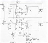
K-12M Schematic
The schematic for RV-D (10/5/01) can be found at:
http://lib1.store.vip.sc5.yahoo.com/lib/webtronics/km12sch.jpg
I have scanned RV-E (5/7/02) and attached it below.
The only difference I see between RV-D and RV-E is the addition of C10 and C11, which are 33pf ceramic capacitors.
Cheers,
Gio.
The schematic for RV-D (10/5/01) can be found at:
http://lib1.store.vip.sc5.yahoo.com/lib/webtronics/km12sch.jpg
I have scanned RV-E (5/7/02) and attached it below.
The only difference I see between RV-D and RV-E is the addition of C10 and C11, which are 33pf ceramic capacitors.
Cheers,
Gio.
Attachments
Re: mods.
Yep, so don't touch them! What I meant before was, whether you were able to touch the transformer, not the valves.
They may be necessary if your source has enough DC on its outputs to mess up the operating point of the input valve, and since this is DC coupled to the phase splitter (Williamson-style) you might mess things up there too. That's why they were put there in the first place. Make sure there is no DC on the outputs of your CDP or pre or whatever before you remove the input caps.
A single fast diode is enough as shown on the Voltsecond site, but I suppose you could change them all.
This is triode-strapping the output valves. So, it means less power from the amp and more drive is needed to the output valves. Open-loop distortion will also be lowered.
You may end up with any of excessive gain, compromised frequency response, or higher output impedance. I wouldn't do this unless you triode-strap the output stage, which in itself will reduce gain and decrease output impedance.
noisenyc said:the bulb temp of tubes is quite high, over 200 degress....normal.
Yep, so don't touch them! What I meant before was, whether you were able to touch the transformer, not the valves.
noisenyc said:i would suggest as mods...
bypass input caps (not necessary).
They may be necessary if your source has enough DC on its outputs to mess up the operating point of the input valve, and since this is DC coupled to the phase splitter (Williamson-style) you might mess things up there too. That's why they were put there in the first place. Make sure there is no DC on the outputs of your CDP or pre or whatever before you remove the input caps.
noisenyc said:replace diodes with hexfreds.
A single fast diode is enough as shown on the Voltsecond site, but I suppose you could change them all.
noisenyc said:disconnect screen supply to power tubes and tie the screens to the plates with 100 ohm resistors.
This is triode-strapping the output valves. So, it means less power from the amp and more drive is needed to the output valves. Open-loop distortion will also be lowered.
noisenyc said:remove negative feedback resistor from the output tap.
You may end up with any of excessive gain, compromised frequency response, or higher output impedance. I wouldn't do this unless you triode-strap the output stage, which in itself will reduce gain and decrease output impedance.
Re: Re: mods.
series caps on the input are there to block incoming DC from the previous stage, which is very unlikely to be there in any significant amount. they will degrade the sonics without a doubt. in fact they are rarely seen even on seriously fancy-dan amps...
it is possibly to somewhat decouple diode noise from the PS with a single series diode but i prefer to eliminate it altogether by making a bridge with four freds...or better yet install tube rectification...
re: the NFB, don't remove it unless you do the triode strapping first.
the combo of those two will decrease output power and increase overall gain (fact), and drastically inprove the sonics (imho).
you will lose 3 db at the speaker before distortion but gain a great sonic improvement, and possibly avoid eviction
gmilitano said:
Hi Blackie,
Why are the input caps not required?
The diode is a single bridge. I was considering the UF4007 mod as proposed Voltsecond.
What would be the purpose of removing the negative feedback resistor?
I will post the new schematic.
Cheers,
Gio.
series caps on the input are there to block incoming DC from the previous stage, which is very unlikely to be there in any significant amount. they will degrade the sonics without a doubt. in fact they are rarely seen even on seriously fancy-dan amps...
it is possibly to somewhat decouple diode noise from the PS with a single series diode but i prefer to eliminate it altogether by making a bridge with four freds...or better yet install tube rectification...
re: the NFB, don't remove it unless you do the triode strapping first.
the combo of those two will decrease output power and increase overall gain (fact), and drastically inprove the sonics (imho).
you will lose 3 db at the speaker before distortion but gain a great sonic improvement, and possibly avoid eviction
Re: Re: Re: mods.
I conversed with VoltSecond via email and apparantly there are some new mods in the works. I did not get any details, but he is trying out some larger PS filtering caps.
Blackie,
Before I get rid of the coupling caps completely, I want to try out some film and foil caps to see if that makes any noticeable improvements.
Also, the VoltSecond site does a good job in arguing that only one diode is needed. Tube rectification would be ideal, but likely a little to advanced for me right now and this is only a $139 amp!
I was skeptical that a $139 tube amp would sound much better than a typical SS amp. However, I am shocked with how much of an improvement this tube amp is over my various mass market SS amps.
I'm glad to say I am a convert!
Happy New Year,
Gio.
Re: Re: Re: Re: mods.
happy new year gio!
i did see the voltsecond mods...but my suggestion was made with this in mind: rather than reduce diode noise somewhat by adding a mess of cheap parts, better to eliminate it altogether with fewer parts.
the cost difference ain't that much!
but hey, i just saw diodes and snubbers in a $4500 Cary 300B amp!
gmilitano said:Blackie,
Before I get rid of the coupling caps completely, I want to try out some film and foil caps to see if that makes any noticeable improvements.
Also, the VoltSecond site does a good job in arguing that only one diode is needed. Tube rectification would be ideal, but likely a little to advanced for me right now and this is only a $139 amp!
I was skeptical that a $139 tube amp would sound much better than a typical SS amp. However, I am shocked with how much of an improvement this tube amp is over my various mass market SS amps.
I'm glad to say I am a convert!
Happy New Year,
Gio.
happy new year gio!
i did see the voltsecond mods...but my suggestion was made with this in mind: rather than reduce diode noise somewhat by adding a mess of cheap parts, better to eliminate it altogether with fewer parts.
the cost difference ain't that much!
but hey, i just saw diodes and snubbers in a $4500 Cary 300B amp!
Re: Re: Re: Re: Re: mods.
With regards to the input coupling capacitors, what would be the source of DC that they would need to block?
Also, what did you have in mind regtification for the power supply.
Regards,
Gio.
noisenyc said:
but hey, i just saw diodes and snubbers in a $4500 Cary 300B amp!
With regards to the input coupling capacitors, what would be the source of DC that they would need to block?
Also, what did you have in mind regtification for the power supply.
Regards,
Gio.
Re: Re: Re: Re: Re: Re: mods.
it is possible that there might be a small dc offset originatingin the output stage of a cd player or preamp caused by poor design or failure due to poor design.
if that were so, you would hear it when you rotate the input pot as "scratchiness".
pretty unlikely. if you look at the input stage of most tube amp designs, you will find no caps.
you can get these to replace the diodes:
http://www.digikey.com/scripts/dksearch/dksus.dll?Detail?Ref=158606&Row=255948&Site=US
they make no diode noise. fast recovery epitaxial diodes.
gmilitano said:
With regards to the input coupling capacitors, what would be the source of DC that they would need to block?
Also, what did you have in mind regtification for the power supply.
Regards,
Gio.
it is possible that there might be a small dc offset originatingin the output stage of a cd player or preamp caused by poor design or failure due to poor design.
if that were so, you would hear it when you rotate the input pot as "scratchiness".
pretty unlikely. if you look at the input stage of most tube amp designs, you will find no caps.
you can get these to replace the diodes:
http://www.digikey.com/scripts/dksearch/dksus.dll?Detail?Ref=158606&Row=255948&Site=US
they make no diode noise. fast recovery epitaxial diodes.
Re: Re: Re: Re: Re: Re: Re: mods.
Ok. How could I go about checking if there is DC from the source? Would a voltmeter on the CD outputs do the trick?
Will the only result be "scratchiness" when changing the volume or will the lack of caps affect the overall sound quality if DC is present?
Are those diodes much better than the UF4007?
Regards,
Gio.
audiousername said:
They may be necessary if your source has enough DC on its outputs to mess up the operating point of the input valve, and since this is DC coupled to the phase splitter (Williamson-style) you might mess things up there too. That's why they were put there in the first place. Make sure there is no DC on the outputs of your CDP or pre or whatever before you remove the input caps.
Ok. How could I go about checking if there is DC from the source? Would a voltmeter on the CD outputs do the trick?
noisenyc said:
it is possible that there might be a small dc offset originatingin the output stage of a cd player or preamp caused by poor design or failure due to poor design.
if that were so, you would hear it when you rotate the input pot as "scratchiness".
pretty unlikely. if you look at the input stage of most tube amp designs, you will find no caps.
you can get these to replace the diodes:
http://www.digikey.com/scripts/dksearch/dksus.dll?Detail?Ref=158606&Row=255948&Site=US
they make no diode noise. fast recovery epitaxial diodes.
Will the only result be "scratchiness" when changing the volume or will the lack of caps affect the overall sound quality if DC is present?
Are those diodes much better than the UF4007?
Regards,
Gio.
dc offset and freds
you can measure dc offset with your voltmeter.
its presence would cause a shift in operating point of the first 2 gain stages of the amp (they a direct coupled) proportional to the amount of dc.
the freds are better (i.e. less noisy) than uf series diodes, and they only cost $1.08 each. they have virtually no switching noise.
cheap insurance as they say...
search digi-key, part number DSEI8-06A-ND.
More K-12M Modifications
For those of you who have one of the K-12M kits and are interested in modifications, VoltSecond has added a few more to his page.
http://www.siteswithstyle.com/voltsecond/K-12M_AMP/K-12M_Push_Pull.html
I hope to try some of the mods out soon.
Cheers,
Gio.
For those of you who have one of the K-12M kits and are interested in modifications, VoltSecond has added a few more to his page.
http://www.siteswithstyle.com/voltsecond/K-12M_AMP/K-12M_Push_Pull.html
I hope to try some of the mods out soon.
Cheers,
Gio.
Re: Re: Re: Re: Re: Re: Re: mods.
Blackie,
The URL is giving me a "Your dataset has expired" message... what are you sending us to look at (i'll have to get some and try them)
dave
noisenyc said:you can get these to replace the diodes:
http://www.digikey.com/scripts/dksearch/dksus.dll?Detail?Ref=158606&Row=255948&Site=US
they make no diode noise. fast recovery epitaxial diodes.
Blackie,
The URL is giving me a "Your dataset has expired" message... what are you sending us to look at (i'll have to get some and try them)
dave
- Status
- This old topic is closed. If you want to reopen this topic, contact a moderator using the "Report Post" button.
- Home
- Amplifiers
- Tubes / Valves
- S-5 Electronics K-12M (11MS8) 8 wpc PP Tube Amp Kit ($139)