Hi there,
I have built a simple cascode line preamp using split rails. The rails are flatline quiet. Also there is absolutely no hum coming in on the input. The whole circuit is only referenced to ground at the stepped attenuator. The circuit ground is isolated from the case ground by a combination of parallel reversed diodes, a 0.22uf cap and a 100ohm resistor.
The heater supply is floating.
Now the funny thing is that the tubes are generating there own mains hum. I say this because as I said the circuit doesn't have any hum on any of its input (I tested this on the scope). I can only assume that the tube itself is picking up hum from the transformers and amplifying it. I grounded the valve base (which was showing quite a significant hum pickup), and also grounded the screen between the two halves of the the valve. The case is connected to socket earth just next to the socket, but nowhere else.
The main transformer runs hot and is a little buzzy.
Do you think moving the case earth will help ? Is this unusual
Here is a version of the circuit.
I now have it running at +/- 85V and pushing 6mA. The grid resistor on the input is now 1.2K instead of the 3.9K. It has a valve rectified supply using UY85's
Sounds better than the +/-50V version.
Any help appreciated.
Shoog
I now have it running at +/- 85V and pushing 6mA. The grid resistor on the input is now 1.2K instead of the 3.9K. It has a valve rectified supply using UY85's
Sounds better than the +/-50V version.
Any help appreciated.
Shoog
Attachments
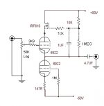
Hey there......that 1M input resistor of the lower tube is wide open for stray noise pickup......you can decouple a current source for at least reduce the effects from noise. With each side at +/0 50v the heater should ground #OV referenced. Look at the figure for heater/cathode isolation spec on tube data sheet. 50V is the limit for a raft of tubes.
The effect of grounding the valve sockets is a sure indication of sensitivity to pickup.
rich
The effect of grounding the valve sockets is a sure indication of sensitivity to pickup.
rich
It based on Joe Rasmussens (it that the correct spelling) Constant Current, Constant Voltage Valve Buffer. The Mosfet doesn't need any more headroom because the scope says it is doing its job just dandy. The circuit works with an input signal of 1V so it should be well within its capablities.
I will definately try using a direct grid connection on the bottom valve, and will try grounding the heater supply, just for the valves sake.
The circuit sits just nicely with the main valve biased at -2V and the CCS at -2.0V. If I were to start messing about with the bias point of the Mosfet, I would loose the valve bias points, and then be into the real of using uneven rails (which I had to do with the +/-50V version).
The current build of the preamp itself is a little physically unstable so a complete rebuild is called for.
Shoog
Don't know about the science of this, but I had a similar problem with my line stage (single 2c22) where like yourself, I had established that the input and ht rails were all quiet. In my case the problem was the floating heater supply and the hum disappeared when one side was grounded. It was a DC heater supply so not exactly sure what was going on. Anyway, maybe worth investigating...
Yes, try referencing the heater to some DC potential. It might be some manifestation of heater/cathode leakage. If it is possible without exceeding the max heater/cathode leakage (I'm posting this quickly, and haven't checked) try referencing the heater to some voltage higher than that of the cathode. Basically (I think) this is because you have a hot heater, and a cooler cathode. The heater may emit electrons to the inner part of the cathode through thermionic emission if it is at a lower potential (forming a conducting diode), while if it is referenced to a higher potential the 'diode' is turned off. That theory is from something I read somewhere - can't remember where. It sounds a little dodgy because the cathode is hot as well, and the 'diode' might actually conduct in both directions if the inner surface of the cathode emits electrons... Try it anyway if you've exhausted some other alternatives.
Thanks for the useful input. I just wanted to point out that the Mosfet is biased at about 4V in the current circuit so the voltage divider should be adjiusted for this working point.
I have a strong feeling that the CCS grid stopper resistor is probably a large part of the problem, so this is where I will look first. The heater is DC so it should be easy to reference it to something. Even if tied to ground I seem to remember that it can take well over a 100V of cathode to heater differnce, I will check the data sheet.
By the way, its well worth trying as it sounds nice and mellow and full. I think trying the valve rectification has smoothed the sound out without killing the detail.
Shoog
Turns out that the problem was the heater supply. I hadn't tied it to earth at any point (I originally was intending to tie one of the DC rails to earth, but forgot). In the end I referenced both rails to ground, via big caps, and left the rails floating. Quiet preamp, Happy me !!!
Thanks for the ideas.
Shoog
Thanks for the ideas.
Shoog
Now come on shooq and the rest of you guys!
More like a blunder! Y'all should know better!
The voltage +/- between the heaters and cathodes of the 6922 in this circuit is well within it's ratings.
Try placing a 100nf 1-2kV ceramic cap across the secondaries that are being rectified and/or some snubbers across the SS rectumfriers, it may help.
Cheers
Wayne
Originally posted by sch3mat1c
and your floating heaters are a red herring.
More like a blunder! Y'all should know better!
The voltage +/- between the heaters and cathodes of the 6922 in this circuit is well within it's ratings.
The main transformer runs hot and is a little buzzy.
Try placing a 100nf 1-2kV ceramic cap across the secondaries that are being rectified and/or some snubbers across the SS rectumfriers, it may help.
Cheers
Wayne
You have misread the data sheet. In a typical application the ECC88 would be well within its heater to cathode range. However in this application with 90V split rails it doesn’t. The bottom triode should have a heater to cathode voltage of max +/- 50V, the top triode should be within +150V. So with the heater around the ground potential the bottom triode is -40V outside its range.
I don’t know how much of a problem this will turn out to be, it certainly doesn’t seem to have an audable effect. However I tried using AC heaters and there was a loud hum pick up (which there shouldn’t be as these valves are designed for AC use and should be nearly quiet with AC supplies).
What is most important is am I damaging the Valves.
Shoog
Shoog said:You have misread the data sheet. In a typical application the ECC88 would be well within its heater to cathode range.
Yes your'e right I forgot to add... since I have alot of ECC88's ;I'm using them with 2 sep heater supplies.........annoying but easy way round the prob.
cheers rich
- Status
- This old topic is closed. If you want to reopen this topic, contact a moderator using the "Report Post" button.
- Home
- Amplifiers
- Tubes / Valves
- **** another unusual hum problem !!