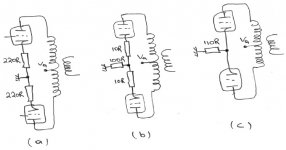
Can you tell me the differences between those three bias arrangements?
The bias point is the same but with different resistor arrangement.
I didn’t put the bypass cap or caps. I’d like to know the differences with the circuits bypassed and un-bypassed.
Which from the three is the best and why? At first glance, I thought that these three are the same because the bias is the same but they’re NOT.
At the second circuit some guys put 10R resistor and some other 33R or other values. Is this value critical or not?
(Of course I know that if you change this value you must change the other resistor to have the same bias point.)
Attachments
Hi,
Well, you should have left them in as that's where the differences lay for some.
a) separate cathode resistors for each tube, better than c) IMO which sports a common resistor for both tubes.
b) I assume the bottom resistors to be capacitively bypassed, the 10R (or higher) separate cathode resistors provide some current feedback. A topology not uncommon in transistorized circuits.
c) The most common and most economical way. Soundwise I don't like it but YMMV.
Another way, there's more than one way to skin the proverbial cat, is to use method b) or a combination of b) and c) where the smaller resistors are adjustable to counteract tube inbalances.
My prefered way is to use fixed bias.
Although it's the more expensive one it does away with the need for bypassing the cathode resistors (recommended) with the never perfect caps and is slightly more efficient and to my ears sounds better too.
Cheers,")
I didn’t put the bypass cap or caps.
Well, you should have left them in as that's where the differences lay for some.
a) separate cathode resistors for each tube, better than c) IMO which sports a common resistor for both tubes.
b) I assume the bottom resistors to be capacitively bypassed, the 10R (or higher) separate cathode resistors provide some current feedback. A topology not uncommon in transistorized circuits.
c) The most common and most economical way. Soundwise I don't like it but YMMV.
Another way, there's more than one way to skin the proverbial cat, is to use method b) or a combination of b) and c) where the smaller resistors are adjustable to counteract tube inbalances.
My prefered way is to use fixed bias.
Although it's the more expensive one it does away with the need for bypassing the cathode resistors (recommended) with the never perfect caps and is slightly more efficient and to my ears sounds better too.
Cheers,
Circuit (a) provides individual cathode bias for each tube. If one tube stops conducting for any reason, the other tube won't be harmed. Without bypass capacitors, there will be current negative feedback, which will reduce the gain significantly and increase the effective plate impedance by an amount = Rk * (mu+1). With or without bypass capacitors, circuit (a) helps to balance the tubes. Mild class AB1 is possible with circuit (a) provided you use large bypass capacitors. This is probably the best arrangement for cathode biasing OP tubes.
Circuit (b) doesn't make a lot of sense to me. The only reason I can think of for having the 10 ohm resistors in there is to provide a means of measuring the cathode current of each tube independently, for checking the balance. Otherwise, in effect it's the same as circuit (c).
Circuit (c) provides a shared cathode bias for the tubes. If one tube should stop conducting, damage could result to the other tube because it will be under-biased - this is mainly true of output tubes, which are commonly biased close to their maximum dissipation. Circuit (c) doesn't help with tube balancing. Although, in theory, the shared cathode resistor doesn't need bypassing, in practice it may be necessary to improve the sound in cases where the tubes themselves are not exactly balanced.
Thank you guys for the theory. I knew it but the reason I ask this question was to hear the comments about tubes balancing.
So the best way for tubes balancing is (a).
I thought it was (b).
Here I have another question.
What do you say about matched pairs that a lot of companies out there sell?
Is it necessary to try to find only matched pairs for better performance?
Suppose we buy a matched pair. Will this matched pair be matched in one or two months? Are tubes getting older the same? Or over here we have another myth?
@fdegrove
I think circuits with self bias have more stability than those with fixed bias.
And are simpler to build, too.
I haven’t tried to build with fixed bias, though. So, what do you say? Give it a try in the future?
Hi,
Depends on how you do it but basically I see no reason for less stability with a fixed bias set-up.
True but I think it gained popularity with most manufacturers because of its reduction in cost....Pennypinchers, ya know.
Why not? Easy enough to try it out for yourself.
Cheers,
I think circuits with self bias have more stability than those with fixed bias.
Depends on how you do it but basically I see no reason for less stability with a fixed bias set-up.
And are simpler to build, too.
True but I think it gained popularity with most manufacturers because of its reduction in cost....Pennypinchers, ya know.
So, what do you say? Give it a try in the future?
Why not? Easy enough to try it out for yourself.
Cheers,
Matched pairs do not usually stay that way for long but at least they'll tend to stay closer than two tubes which started out differently. How well the matching works depends on who did the matching and what procedure they used. If I'm using tubes which aren't hideously expensive, I'll buy about twice what I need and match them myself at the desired operating point.
Do use cathode bypass caps!
And I've been toying with a new way to do cathode bias- if all goes well this weekend, I might be able to see if it actually works...
Do use cathode bypass caps!
And I've been toying with a new way to do cathode bias- if all goes well this weekend, I might be able to see if it actually works...
Biasing
Hello ,
The Williamson biasing scheme is a good starting place for cathode bias but for low ra valves I prefer a compound bias scheme using a CCS tail and variable grid bias . Always find it best to use an adjustable system with a single tail that does not use bypass caps , I'd love to try Blackgates but just can't justify the cost ! Everything I build also uses bias meters , very useful for real-time balancing , also if the output stage is biased into class A the meter dancing from side to side indicates clipping . One point to note , if high slope low mu valves are used such as 6C33 , best to use the compound scheme mentioned otherwise HT is being thrown away heating up the cathode bias resistors .
cheers
SY said:Matched pairs do not usually stay that way for long but at least they'll tend to stay closer than two tubes which started out differently. How well the matching works depends on who did the matching and what procedure they used. If I'm using tubes which aren't hideously expensive, I'll buy about twice what I need and match them myself at the desired operating point.
Do use cathode bypass caps!
And I've been toying with a new way to do cathode bias- if all goes well this weekend, I might be able to see if it actually works...
Hello ,
The Williamson biasing scheme is a good starting place for cathode bias but for low ra valves I prefer a compound bias scheme using a CCS tail and variable grid bias . Always find it best to use an adjustable system with a single tail that does not use bypass caps , I'd love to try Blackgates but just can't justify the cost ! Everything I build also uses bias meters , very useful for real-time balancing , also if the output stage is biased into class A the meter dancing from side to side indicates clipping . One point to note , if high slope low mu valves are used such as 6C33 , best to use the compound scheme mentioned otherwise HT is being thrown away heating up the cathode bias resistors .
cheers
@SY
@316a
Can you post any schem of your output stage?
It’s very interesting using a CCS tail and a variable grid bias!
What kind of CCS are you using?And what kind of variable grid bias?
But I like very much your idea with CCS tail.
Of cource,I'll use bypass caps. I draw the schems just to saw you the resistors arrangement.Do use cathode bypass caps!
Will you post it to diyaudio??????And I've been toying with a new way to do cathode bias- if all goes well this weekend, I might be able to see if it actually works...
@316a
Can you post any schem of your output stage?
It’s very interesting using a CCS tail and a variable grid bias!
What kind of CCS are you using?And what kind of variable grid bias?
Very cool!Everything I build also uses bias meters , very useful for real-time balancing , also if the output stage is biased into class A the meter dancing from side to side indicates clipping .
Yes they're too expensive.I'm planning to use NIPPON caps bypassed with Audyn MKP.I'd love to try Blackgates but just can't justify the cost !
But I like very much your idea with CCS tail.
I'll post the idea now, since it's possible that my wife will intercept all my efforts to get a few hours of work in ("But, it's SHOPPING weekend!!!"): an array of LEDs. With red LEDs, for example, you get about 1.7V drop. So five in series will have an impedance of something like 25 ohms and a drop of 8.5V, about right for an EL84. But wait! The LEDs are happy at a 20mA current, so four strings in parallel could handle the max current of a pair of EL84s and at the same time, drop the string impedance to roughly 6 ohms.
Now, this is 20 LEDs per pair of tubes. Fortunately, LEDs are small, so this could be built up on a 3cm square piece of perfboard, which isn't much larger than a power resistor. And at about 10 cents apiece in a bulk pack at my local parts emporium, the cost per side is about $2, which is pretty good compared to a non-inductive wirewound and a high quality bypass. Overload performance ought to be spectacular- instant overload recovery with no time constant.
The downside will no doubt be the dazzling light.
Funny light-bulbs
Hello ,
Interesting ! Never even considered LEDs for an output stage .
...but how do the b*ggers sound and measure ?
Dave Slagle mentioned using coloured lightbulbs for cathode bias a while ago on the Audioasylum .
...suppose Christmas tree lights could also be used
cheers
SY said:I'll post the idea now, since it's possible that my wife will intercept all my efforts to get a few hours of work in ("But, it's SHOPPING weekend!!!"): an array of LEDs. With red LEDs, for example, you get about 1.7V drop. So five in series will have an impedance of something like 25 ohms and a drop of 8.5V, about right for an EL84. But wait! The LEDs are happy at a 20mA current, so four strings in parallel could handle the max current of a pair of EL84s and at the same time, drop the string impedance to roughly 6 ohms.
Now, this is 20 LEDs per pair of tubes. Fortunately, LEDs are small, so this could be built up on a 3cm square piece of perfboard, which isn't much larger than a power resistor. And at about 10 cents apiece in a bulk pack at my local parts emporium, the cost per side is about $2, which is pretty good compared to a non-inductive wirewound and a high quality bypass. Overload performance ought to be spectacular- instant overload recovery with no time constant.
The downside will no doubt be the dazzling light.
Hello ,
Interesting ! Never even considered LEDs for an output stage .
...but how do the b*ggers sound and measure ?
Dave Slagle mentioned using coloured lightbulbs for cathode bias a while ago on the Audioasylum .
...suppose Christmas tree lights could also be used
cheers
316a's 'Compound bias scheme'
Hello ,
Already have , it's in the archives somewhere (about two years ago) . Pretty simple : join cathodes with 4.7 ohm resistors , connect centre-reading meter between cathodes , connect centre of resistors to CCS . Apply variable bias to the grids . CCS usually needs around 20V to operate correctly , so say for example -50V bias is required , the grids need to have -30V applied to them (in other words -15v to -45V from a pair of pots) This way dissipation of the CCS is reduced , less HT is wasted 'heating' the CCS and any imbalance can be nulled reducing DC in the transformer core) . I usually act lazy and use a single DN2540 depletion mosfet but a battery biased IRF720 also works a treat . Power output gets severely sapped , only class A operation is allowed but to me , it sounds very good ! You can't just stuff a CCS tail under your chosen output stage , the output transformer's impedence needs to be taken into careful consideration . Suppose this could also be sued for SE if the CCS is bypassed but thats not my cup of tea
cheers
316a
resident said:[B@316a
Can you post any schem of your output stage?
It’s very interesting using a CCS tail and a variable grid bias!
What kind of CCS are you using?And what kind of variable grid bias?
Very cool!
[/B]
Hello ,
Already have , it's in the archives somewhere (about two years ago) . Pretty simple : join cathodes with 4.7 ohm resistors , connect centre-reading meter between cathodes , connect centre of resistors to CCS . Apply variable bias to the grids . CCS usually needs around 20V to operate correctly , so say for example -50V bias is required , the grids need to have -30V applied to them (in other words -15v to -45V from a pair of pots) This way dissipation of the CCS is reduced , less HT is wasted 'heating' the CCS and any imbalance can be nulled reducing DC in the transformer core) . I usually act lazy and use a single DN2540 depletion mosfet but a battery biased IRF720 also works a treat . Power output gets severely sapped , only class A operation is allowed but to me , it sounds very good ! You can't just stuff a CCS tail under your chosen output stage , the output transformer's impedence needs to be taken into careful consideration . Suppose this could also be sued for SE if the CCS is bypassed but thats not my cup of tea
cheers
316a
LEDs for bias = bad.
Why? Because they will *modulate* with a 50/60Hz. light flicker!
This was found to be happening many years back when Spectral made some preamps with nice lucite tops to show off the nice PCBs and layout...
Fluorescent lights flicker, modulate the LEDS!
(btw, I'm a fan of fixed bias for output stages)
_-_-bear
Well, the question is how much does the resistance get modulated and how significant is that compared with the impedances in the circuit? Given that we're talking about a couple of ohms as baseline, I'll bet this effect is negligible in this application, and certainly less important than the problems with blocking that RC bias brings to the mix. But experiment will prove or disprove my belief.
resident said:Yes they're (Blackgates) too expensive.
And getting pretty close to unobtainum... as soon as it was announced that their manufacture would cease, all but the least common values were scooped up.
dave
bear said:[Fluorescent lights flicker, modulate the LEDS!
Couldn't that be solved by just making sure the LEDs never see a flourescent light?
dave
SY said:With red LEDs, for example, you get about 1.7V drop. So five in series will have an impedance of something like 25 ohms and a drop of 8.5V, about right for an EL84. But wait! The LEDs are happy at a 20mA current
Here is a chart Morgan Jones presented at the most recent ETF... only goes up to 15 mA thou. An EL84 will bias somewhere circs 38-42 mA (in Class A).
dave
Attachments
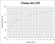
Looking at the slope past 8 mA, it sure looks like the 5 ohm estimate is a good one. So, if the 60Hz modulates it by 10% (which I think is a gross overestimate), that means that the array I proposed for the EL84s will bounce up and down by 0.6ohm times .08A which is about 50 mV. That could well be audible.
Bear, do you have any info on how much the LEDs' resistance actually gets modulated at typical ambient intensities? If not, it should be relatively easy to measure. And I think that the array's light output might tend to swamp the ambient energy, but....
Bear, do you have any info on how much the LEDs' resistance actually gets modulated at typical ambient intensities? If not, it should be relatively easy to measure. And I think that the array's light output might tend to swamp the ambient energy, but....
SY said:And I think that the array's light output might tend to swamp the ambient energy, but....
Especially if it is only lighting up the inside of the box...
dave
Hi,
Ah...Thanks for reminding us why they're bad.
I vaguely remembered they were to be avoided, thought it was for "noise" reasons but had forgotten why.
Don't know if you noticed but we had a thread running about them a while ago already.
Probably in the "Electonic Parts" section of the forum, haven't double checked.
Anyway, if they're tucked away neatly under the bonnet I suppose they only contribute they're own "self-generated" noise.
Something that can safely be ignored in the case of biasing an output section of an amp, I presume...........
Cheers,
This was found to be happening many years back when Spectral made some preamps with nice lucite tops to show off the nice PCBs and layout...
Ah...Thanks for reminding us why they're bad.
I vaguely remembered they were to be avoided, thought it was for "noise" reasons but had forgotten why.
Don't know if you noticed but we had a thread running about them a while ago already.
Probably in the "Electonic Parts" section of the forum, haven't double checked.
Anyway, if they're tucked away neatly under the bonnet I suppose they only contribute they're own "self-generated" noise.
Something that can safely be ignored in the case of biasing an output section of an amp, I presume...........
Cheers,
- Status
- This old topic is closed. If you want to reopen this topic, contact a moderator using the "Report Post" button.
- Home
- Amplifiers
- Tubes / Valves
- bias arrangements for P-P amps.