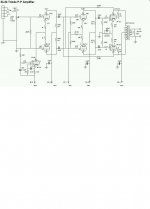
My 6SL7 LTP splitter, with CCS in the tail, is DC coupled to a 6SN7 differential driver. The 6SL7 plate voltages are within 3% ") . However, I find a much larger DC offset of about 20% at the plates of the 6SN7 . For the 6SN7, the load resistors are 33k and there is a 30k tail resistor, which goes to -120v line, with separate 220 ohm resistors between the top of the tail resistor and each 6SN7 cathode. I'm pretty sure that the imbalance is due to the tube, not circuit resistor tolerances.
. However, I find a much larger DC offset of about 20% at the plates of the 6SN7 . For the 6SN7, the load resistors are 33k and there is a 30k tail resistor, which goes to -120v line, with separate 220 ohm resistors between the top of the tail resistor and each 6SN7 cathode. I'm pretty sure that the imbalance is due to the tube, not circuit resistor tolerances.
What is the best way of mimizing this offset, apart from changing the tube? Should I make the 6SN7's individual cathode resistors larger? Put a balancing pot between the cathodes of the 6SL7, with the slider going to the CCS tail? Any other suggestions? Or is DC coupling just not worth the bother? (I could use a step network, for example).
I thought this was worth a separate thread because, although it arose from trying to apply effective local feedback (as suggested by KYW), it's really a different topic.
. However, I find a much larger DC offset of about 20% at the plates of the 6SN7 . For the 6SN7, the load resistors are 33k and there is a 30k tail resistor, which goes to -120v line, with separate 220 ohm resistors between the top of the tail resistor and each 6SN7 cathode. I'm pretty sure that the imbalance is due to the tube, not circuit resistor tolerances.What is the best way of mimizing this offset, apart from changing the tube? Should I make the 6SN7's individual cathode resistors larger? Put a balancing pot between the cathodes of the 6SL7, with the slider going to the CCS tail? Any other suggestions? Or is DC coupling just not worth the bother? (I could use a step network, for example).
I thought this was worth a separate thread because, although it arose from trying to apply effective local feedback (as suggested by KYW), it's really a different topic.
Dude
I made a dc coupled ltp with even a ccs and the voltage on the plate drift and were not stable and not balance. Also please note u can only get either dc balanced or ac balanced only not both. In the end it sounded great but i was pulling out lots of hair back then when making the stuff. To balance the dc i use a variable resistor at the plate. What u do is connect your plate resistors to this variable resistor and tune until the cows come home. I will never again recommend this stupid design anymore to anyone even though it sounds superb. After 3 months have to rebias the tube again.
For more information check out
www.geocities.com/nickchua81
it is there somewhere under my el34 pp
Cheers
Bad circuits 101
Ouch... bad circuits 101 this thread shall be called.
Use coupling caps. DC coupling is for situations that need it, like my active preamp circuit, which has no room for unstable coupling cap phase shifts, or power supplies which obviously must be DC coupled. Or just use a simpler, more effective circuit (my 31LQ6 PP schematic, vs. a standard Williamson driver).
If you ABSOLUTELY MUST DO THIS, you need to apply feedback which first takes the DC difference and couples it back to the input, the unused inverting input if you are using only the + input. Reason being is the circuit is doing exactly what you asked it to, amplify the difference in the 6SL7's. And it sounds like it is doing an admirable job.
Tim
Konnichiwa,
First, you are right, it is to do with tube tolerances. You probably had nearly as much difference between the Anodes in the previous circuit. In my own design I have tested many 6SL7/6SN7's and I find around 1 in 20 of current proiduction chinese Tubes are out "too far". They are also rather far out in the AC coupled Amp's. So don't worry too much, get a few more 6SN7's, preferably selected for good match between sections at the current/voltage you use.
You can connect a 470R trimmer between the two 1K resistors in the 6SL7 tail to trim out the differences, I personally choose a very different approach (as you have seen) which acually in practice offers a more reliable DC Balance in the input and driver pair due to a number of circuit features.
Sayonara
ray_moth said:My 6SL7 LTP splitter, with CCS in the tail, is DC coupled to a 6SN7 differential driver. The 6SL7 plate voltages are within 3%
First, you are right, it is to do with tube tolerances. You probably had nearly as much difference between the Anodes in the previous circuit. In my own design I have tested many 6SL7/6SN7's and I find around 1 in 20 of current proiduction chinese Tubes are out "too far". They are also rather far out in the AC coupled Amp's. So don't worry too much, get a few more 6SN7's, preferably selected for good match between sections at the current/voltage you use.
You can connect a 470R trimmer between the two 1K resistors in the 6SL7 tail to trim out the differences, I personally choose a very different approach (as you have seen) which acually in practice offers a more reliable DC Balance in the input and driver pair due to a number of circuit features.
Sayonara
ouch!Dude
double ouch!!Ouch... bad circuits 101 this thread shall be called.

Your points are well taken. Actually, I was trying to create conditions under which cross-coupled NFB from the OP tube plates to the IP tube plates would be stable. Having coupling caps feeding both the drivers and the OP tubes didn't seem like a good idea.
However, it then occurred to me that, if I take the NFB loop to the driver grids, I could use coupling caps between the splitter and the driver with no ill effects on stability. Of course, I would need a resistor from each driver grid to ground or the negative rail (I chose the latter), so the drivers would be correctly biased. It would also enable me to use a better operating point for the 6SL7 splitter.
Please see attached circuit, which I think solves the problem. Comments are welcome!
Attachments
Looks better
FWIW, your CCS will work better without the grid decouping - the cathode degeneration increases effective Rp. And likewise, you'll get more power output, gain and damping factor by bypassing the EL34 cathodes.
Other than that, it looks good for a nice bit of balanced operation theme.
Tim
FWIW, your CCS will work better without the grid decouping - the cathode degeneration increases effective Rp. And likewise, you'll get more power output, gain and damping factor by bypassing the EL34 cathodes.
Other than that, it looks good for a nice bit of balanced operation theme.
Tim
Konnichiwa,
This is also not particulary difficult to do, I might add. My own circuit uses direct coupling in all positions except between driver anodes and utput stage grids and remains quite well belanced for DC with most valves I tried (includies chinese, sovtek & various NOS).
How about returing the NFB to the input stage anodes? It strikes me as a better solution. That way your coupling cap's remain inside the NFB loop.
Also, do you operate the (Input/Driver) valves at a slightly lowered Heater voltage? It helps stabilise their behaviour, apart from drastically extending their life.
Sayonara
ray_moth said:Actually, I was trying to create conditions under which cross-coupled NFB from the OP tube plates to the IP tube plates would be stable. Having coupling caps feeding both the drivers and the OP tubes didn't seem like a good idea.
This is also not particulary difficult to do, I might add. My own circuit uses direct coupling in all positions except between driver anodes and utput stage grids and remains quite well belanced for DC with most valves I tried (includies chinese, sovtek & various NOS).
ray_moth said:However, it then occurred to me that, if I take the NFB loop to the driver grids, I could use coupling caps between the splitter and the driver with no ill effects on stability.
How about returing the NFB to the input stage anodes? It strikes me as a better solution. That way your coupling cap's remain inside the NFB loop.
Also, do you operate the (Input/Driver) valves at a slightly lowered Heater voltage? It helps stabilise their behaviour, apart from drastically extending their life.
Sayonara
Kuei Yang Wang said:This is also not particulary difficult to do, I might add. My own circuit uses direct coupling in all positions except between driver anodes and utput stage grids and remains quite well belanced for DC with most valves I tried (includies chinese, sovtek & various NOS).
http://webpages.charter.net/dawill/tmoranwms/Circuits/31LQ6_PP.gif
(The exact circuit shown hasn't been built but the driver has, using a 12AU7 instead of 6DJ8; works nicely in the quad 6L6 amp.)
How about returing the NFB to the input stage anodes? It strikes me as a better solution. That way your coupling cap's remain inside the NFB loop.
Ideally you should take a loop from the speaker terminal to the grounded (inverting) input, but that's almost guaranteed to oscillate with two coupling cap stages and an OPT adding up for three phase shifts.
Tim
Konnichiwa,
Not just that, it also a recipy for high livels of TIM/PIM and for a distrotion spectrum with a low absolute THD but high audibility due to the overtone order multiplying effect of the feedback loop.
If we enclose an Amplifier producing pure 2nd harmonics in a feedback loop we get back 2nd, 3rd and 4th harmonics, with a reduced level of 2nd harmonics and higher harmonics down further following a complex function depending upon the amplifier design.
Now if we daisychain two stages we also have a distortion order multiplying process, so 2 stages in series of traditional triodes producing 2nd & 3rd harmonics will actually reduce the 2nd harmonics but produce harmonics out to the 5th. Add a 3rd stage and our harmonics extend to the 7th, add NFB and we get a huge slew of harmonics. How many of these fall below the noisefloor or how audible they are is another interresting story.
But yes, looping a "long" global feedback loop around many non-linear stages and elements is not a smart thing to do, if you concerned about distortion audibility and not just good measurements.
Sayonara
Sch3mat1c said:Ideally you should take a loop from the speaker terminal to the grounded (inverting) input, but that's almost guaranteed to oscillate with two coupling cap stages and an OPT adding up for three phase shifts.
Not just that, it also a recipy for high livels of TIM/PIM and for a distrotion spectrum with a low absolute THD but high audibility due to the overtone order multiplying effect of the feedback loop.
If we enclose an Amplifier producing pure 2nd harmonics in a feedback loop we get back 2nd, 3rd and 4th harmonics, with a reduced level of 2nd harmonics and higher harmonics down further following a complex function depending upon the amplifier design.
Now if we daisychain two stages we also have a distortion order multiplying process, so 2 stages in series of traditional triodes producing 2nd & 3rd harmonics will actually reduce the 2nd harmonics but produce harmonics out to the 5th. Add a 3rd stage and our harmonics extend to the 7th, add NFB and we get a huge slew of harmonics. How many of these fall below the noisefloor or how audible they are is another interresting story.
But yes, looping a "long" global feedback loop around many non-linear stages and elements is not a smart thing to do, if you concerned about distortion audibility and not just good measurements.
Sayonara
How about returing the NFB to the input stage anodes? It strikes me as a better solution. That way your coupling cap's remain inside the NFB loop.
That's what I did at first, when I was using DC coupling between first and second stages. It make no difference then, of course, because the input tube plates and the driver grids are the same point. However, once I introduced the coupling caps from the first to second stages, I returned the NFB loop to the second stage grids specifically to avoid having those coupling caps in the feedback loop. It seemed to me to be a recipe for instability to do otherwise. Anyway, it sounds really good now.
The only things I'm planning to change, as Sch3mat1c has suggested, are:
(a) to remove the 0.1uF decoupling capacitor between grid and cathode of the CCS; and
(b) to bypass the cathodes of the OP tubes fully.
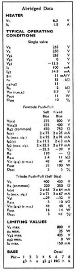
The reason for my unusual arrangement, with half of the cathode resistance commoned and bypassed and the other half separate and unbypassed, is intended as a compromise between Mullard's recommendation for either 5k p-p load with fully bypassed cathode resistors @19 watts or 10k p-p load with unbypassed cathode resistors @14 watts. This is because I'm stuck OPTs that give me 7.5K p-p load, which is halfway.
However, I've just seen another specification by Mullard for EL34s in triode p-p (please see attached), with either 220 ohm using 5k p-p or 250 ohm common cathode resistoror using 10k p-p. With my arrangement of resistors I get the equivalent of 460 ohm, so if I fully bypass each cathode to ground that seems OK as long as I can get more B+.
If this explanation makes no sense, I apologize.
 My excuse is that I'm left-handed
 Attachments
Also, do you operate the (Input/Driver) valves at a slightly lowered Heater voltage? It helps stabilise their behaviour, apart from drastically extending their life.
Yes. In fact, the whole amp. is run from lowered heater voltages. My mains transformers are toroids from Amplimo and the primaries are wound for only one voltage: 230v. Here in Indonesia the standard mains voltage is 220v and it's often a bit lower than that.
- Status
- This old topic is closed. If you want to reopen this topic, contact a moderator using the "Report Post" button.
- Home
- Amplifiers
- Tubes / Valves
- Balancing DC-coupled differential stages