Hey,
I tried to get some help from you guys to design a hybrid-rectified PS at my project thread, " Help need to find..."
But nobody did, so here it is.... I really need help here....
I got a single new transformer with secondaries having no CT.
I can use 4 silicon diodes to form a full-wave bridge. This method allows me to save a lot of space, but I need to get high quality Schottky or Harris diodes, which cost an arm (I need 8 diodes in total to make 2 PS with single transformer!!)...
With this method, I would also have to add a switch on one of the two secondary wires to allow heaters to fully heat-up before HV is applied...
To avoid using the delay switch, I can use small rectifier tubes like EZ80 to make half-wave rectified PS, but the efficiency isn't good at all...
So it comes to a conclusion that I should use hybrid rectification with this secondary winding without a CT. It allows me to use any diode and does not require any delay switch.
It is really cost effective to me, as I already have many tube rectifiers and all I have to buy is 4 silicon diodes in any quality.
I know that this method is normally used with directly-heated rectifiers like 5U4, but why not with indirectly-heated ones?
But it makes me wonder... Is hybrid-rectification suitable with such a minimal approach, using only RC or RCR filter?
As I don't have any more space on the amp chassis, I can't add any choke or more 'large PS caps,' and I can't make a PSU on a separate chassis, as I've already spent quite a lot of money on the amp chassis.
So could you guys let me know whether hybrid-rectification is suitable with simple RC filter?
If IT IS suitable, please please please help me out to design one for my amp...
Here are the things that I have, to be used for the PS:
*12pcs 100ohm 50W Aluminium Clad Dale resistors. I can connect many of these to increase the resistance.
*Many EZ80 rectifiers.
*A pair of MKP 60uF 370VAC motor-run caps.
And here's the secondary winding:
----- 0V
l
l
l---- 167V
l
----- 205V @ 0.25A
It is rated for 205V @ 0.25A (with a tap rated for 167V, but that's not a CT... let's ignore the odd tap and use the 205V one...) I'll use the 0V and 205V taps to use the winding as a simple, two-tapped winding.
Please remeber that this SINGLE transformer will supply BOTH channels. I'll build TWO PSU sharing this single transformer, ONE PS unit for EACH cahnnel.
Thanks guys !!
James
jamesjung21 said:but I need to get high quality Schottky or Harris diodes
No...
(I need 8 diodes in total to make 2 PS with single transformer!!)...
No...
With this method, I would also have to add a switch on one of the two secondary wires to allow heaters to fully heat-up before HV is applied...
No...
I know that this method is normally used with directly-heated rectifiers like 5U4, but why not with indirectly-heated ones?
Because DHT is cheaper and better.
But it makes me wonder... Is hybrid-rectification suitable with such a minimal approach, using only RC or RCR filter?
Electrically it is the exact same as taking a CT'd winding, putting a 5U4 on it, and connecting a silicon diode in series with each plate.
As I don't have any more space on the amp chassis, I can't add any choke or more 'large PS caps,' and I can't make a PSU on a separate chassis, as I've already spent quite a lot of money on the amp chassis.
Ah, a perfect reason for SS.
So could you guys let me know whether hybrid-rectification is suitable with simple RC filter?
The problem with your preceeding statement is the falsity is on the wrong element.
 Although an engineer I can't say either is acceptable...
----- 205V @ 0.25A
...
Please remeber that this SINGLE transformer will supply BOTH channels. I'll build TWO PSU sharing this single transformer, ONE PS unit for EACH cahnnel.
FYI, you'll get maybe 150mA DC output before burning that up too much (assuming it is rated for 250mA AC RMS). You can try pushing 250mADC....but it's your problem if it smokes.
Tim
but I need to get high quality Schottky or Harris diodes
No...
You're right; using any cheap diode like 1N4007 won't do any damage, as long as the diodes' rating is strong enough... But then, I should also use cheap transformer, cheap tubes etc, because using such cheap diodes means I don't care about the quality, as long as the amp makes a sound.
(I need 8 diodes in total to make 2 PS with single transformer!!)...
No...
Yes... Each SS-rectification bridge needs 4 diodes, and I'll be having 2 bridges to make 2 PS, so there are... 4X2= 8 diodes in total.
Because DHT is cheaper and better.
True... 5U4 is really cheap in eBay, compared to GZ34. But why are DH rectifiers better
 Is it because they can be made stronger than those indirectly heated ones?
Electrically it is the exact same as taking a CT'd winding, putting a 5U4 on it, and connecting a silicon diode in series with each plate.
Oh, so you mean I can actually use my previous PS design (RC filter) made for the weak CHICAGO transformer with CT, on this hybrid rectifier by using the 2 silicon diodes' junction (i.e. the point where the two diodes meet together) as the CT/ground?
FYI, you'll get maybe 150mA DC output before burning that up too much (assuming it is rated for 250mA AC RMS). You can try pushing 250mADC....but it's your problem if it smokes
The transformer actually has other sec. windings as well (e.g. 302V @ 0.2A) and I won't be using those windings, as these provide too high-V for my amp... It means I'm having some extra margin in the overall power rating before pushing the transfo too far... It really is much stronger than my previous Chicago one...
Thanks,
James
PS: I had a quick visit to your web... That crucible is interesting indeed... Just wondering how simple propane gas can be strong enough to melt-down those bare metals... I thought only hi-oxi acetylene gas is suitable....interesting... Any plan to form molten iron with "iron oxide VS aluminium" displacement reaction?
What's the best program to simulate a hybrid-rectified PSU?
I need simulated voltage and current readings.
But the problem is 'PSU designer II' won't support hybrid rectification...
That's why I need to buy descent quality diodes, because hi-q diodes tend to have soft-recovery characteristics. And of course, I was going to add snubbing caps, if nobody helps me to confirm that I can use hybrid rect. and have to use silicon dioded bridge...
I need simulated voltage and current readings.
But the problem is 'PSU designer II' won't support hybrid rectification...
Bridge each 1N4007 or whatever you chose with a 0.01 to 0.047uF, 1KV or better capacitor to snub the reverse-recovery transients.
That's why I need to buy descent quality diodes, because hi-q diodes tend to have soft-recovery characteristics. And of course, I was going to add snubbing caps, if nobody helps me to confirm that I can use hybrid rect. and have to use silicon dioded bridge...
jamesjung21 said:You're right; using any cheap diode like 1N4007 won't do any damage, as long as the diodes' rating is strong enough... But then, I should also use cheap transformer, cheap tubes etc, because using such cheap diodes means I don't care about the quality, as long as the amp makes a sound.
Sigh, yet more deep-rooted prejudice against quality components.

Yes... Each SS-rectification bridge needs 4 diodes, and I'll be having 2 bridges to make 2 PS, so there are... 4X2= 8 diodes in total.
And you need two bridges ... why?
True... 5U4 is really cheap in eBay, compared to GZ34. But why are DH rectifiers better
Most likely. Battery power radio tubes are also directly heated unipotential coated (i.e., the white stuff on a cathode applied directly to the filament instead) so there is less waste heat and thus greater efficiency.
Oh, so you mean I can actually use my previous PS design (RC filter) made for the weak CHICAGO transformer with CT
What do you mean by weak? Insufficient for whatever application you are/were eyeing at the time? Or was its regulation exceedingly bad?
I've never seen a transformer which, when used within its ratings, is explicitly "bad". And besides, your concern obviously isn't regulation if you keep bringing up this "RC" acronym...
on this hybrid rectifier by using the 2 silicon diodes' junction (i.e. the point where the two diodes meet together) as the CT/ground?
Yeah. I think. Uh, something like that. Well look at the layout of a normal FWB. Then replace the top two diodes (which rectify the AC legs into the positive rail) with a 5U4/???.
PS: I had a quick visit to your web... That crucible is interesting indeed... Just wondering how simple propane gas can be strong enough to melt-down those bare metals...
Gnaw, you just have to enclose the heat in a furnace. There's a guy somewhere who melted chromium with propane, with an extremely thick furnace mind you!
I thought only hi-oxi acetylene gas is suitable....interesting...
Nah, only for welding in open air with reasonable speed. Plain air/propane works for brass brazing if you're patient.
Any plan to form molten iron with "iron oxide VS aluminium" displacement reaction?
I've tried thermite before but could never get it burning very well...
jamesjung21 said:But the problem is 'PSU designer II' won't support hybrid rectification...
So ignore the diodes, they only produce a 0.7V drop which pales in comparison to not only the tube's drop but the absolute voltage level as well.
That's why I need to buy descent quality diodes, because hi-q diodes tend to have soft-recovery characteristics.
But, any semiconductor diode has the exact same characteristics: exponental turn-on (producing a typical Vf of 0.3-0.4V for germanium and schottky and 0.7V for silicon), a recovery time (to clear the junction of conduction elements, holes or electrons) and a barrier (where there is conductive semiconductor either side of a depleted region). The goal of course is to improve these characteristics, voltage or time-wise. But they still remain no matter what. So you'll need snubbers anyway, which it just so happens are the perfect solution.
And of course, I was going to add snubbing caps, if nobody helps me to confirm that I can use hybrid rect. and have to use silicon dioded bridge...
If you said that in a positive tone I'd say we're done here...
Tim
Hybrid rectification isn't a good idea. You'll have lots of ripple to beat-the-snot outta your filter cap. The SS diodes are going to conduct better at the top, the tube on the bottom of the AC cycle. The waveform will show one half-cycle larger than the other, this is going to turn into a nasty little sawtooth at the filter cap.
Use all SS or all tube, but not both, on the same winding.
Many designers use a hybrid, but on different windings - a 5U4 or 5R4 on the HV winding, SS diodes on the filament windings for DC heaters.
Too bad your limited on space, otherwise I'd suggest using a bridge of horizontal-damper tubes for rectification.
However, in your position, IMHO, just use a bridge of 1N4007.
Hi,
If you mean a setup where you use two diodes and a half wave tube rectifier in a FWB configuration then I don't think there is any such problem as you state.
The silicon diodes will not cause more or less ripple neither will they be the cause of much increased RFI.
In fact the bridge will act as a FW tubed diode bridge with considerably less voltage drop and only slightly more spikes than a FWB uses all tubed diodes.
The idea was originally brought to us here by Gary Pimm and duely explained by him as well.
If you care to look it up I'm sure the local search engine will dig up some relevant info.
Of course the SS diodes can still be snubbed properly and be of high audio quality as well but there's little need for that: a pair of 1N4007s would do very well already.
Cheers,
Hybrid rectification isn't a good idea. You'll have lots of ripple to beat-the-snot outta your filter cap. The SS diodes are going to conduct better at the top, the tube on the bottom of the AC cycle. The waveform will show one half-cycle larger than the other, this is going to turn into a nasty little sawtooth at the filter cap.
If you mean a setup where you use two diodes and a half wave tube rectifier in a FWB configuration then I don't think there is any such problem as you state.
The silicon diodes will not cause more or less ripple neither will they be the cause of much increased RFI.
In fact the bridge will act as a FW tubed diode bridge with considerably less voltage drop and only slightly more spikes than a FWB uses all tubed diodes.
The idea was originally brought to us here by Gary Pimm and duely explained by him as well.
If you care to look it up I'm sure the local search engine will dig up some relevant info.
Of course the SS diodes can still be snubbed properly and be of high audio quality as well but there's little need for that: a pair of 1N4007s would do very well already.
Cheers,
Sch3mat1c said:Gregggggg, you got the FWB 90 degrees sideways. Look again.
Tim
I do?
fdegrove said:Hi,
If you mean a setup where you use two diodes and a half wave tube rectifier in a FWB configuration then I don't think there is any such problem as you state.
Hmmmmm, I'll re-scope the setup I tried.....a 5Y3+2x1N4007. I had killer sawtooth troubles
..... Hey! try and say that fast, three times!
A few quick thoughts
Forgive me if his was already suggested. I just read the initial post containing the question.
You can use four diodes as a bridge on the outside (206V winding terminals). Then use an EZ-80 slow warm-up rectifier (if that is the tube you must use), with plates paralleled for more current capability to each separate amplifier circuit.
The additional use of tube rectifiers will not stop silicon diodes from producing switching noise however. Someone please correct me if I am mistaken. This noise will travel back into the power xfmer and come out the other windings unless you use a transformer with a shielded HV winding. The noise may be attenuated somewhat through the rectifier tubes.
Snubber caps of 0.01 mF value at 1 kV DC rating can be used across each diode to help supress the switching nois. A parallel LC resonant network filter in series with each transformer HV lead tuned to the resonant frequency created between the output winding of the transformer and the stray circuit capacitance (usually 40 KHz to several hundred KHz) can also help keep this garbage out of the transformer. A capacitor across the HV winding of the xfmer alone (try 0.01 uF/1kV) may be enough to do the trick.
You could use one or both of the motor run caps on the output of the SS bridge prior to feeding the anodes of the EZ-80's. A separate electrolytic of a value not exceeding about 47 uF could be used on the cathode outputs of each EZ-80 to act as reservoir filter for the amplifier attached to that rectifier tube.
Although an engineer I ...
Wow - already. Where did you get your degree so fast?
And you need two bridges ... why?
To minimise the interaction or cross-talk between the two channels by using two separate PSU, although both channels are sharing single transformer.
What do you mean by weak? Insufficient for whatever application you are/were eyeing at the time? Or was its regulation exceedingly bad?
Oh, I think you need to read my previous thread...
I had a single chicago transfo, which was too weak (i.e. its HV winding's power rating) to supply both channels by alone. It was 488V CT @ 0.07A.
Yeah. I think. Uh, something like that. Well look at the layout of a normal FWB. Then replace the top two diodes (which rectify the AC legs into the positive rail) with a 5U4/???.
I'll try to draw a diagram and post it here, so that you guys can double check that it is ok (or SAFE!).
I've tried thermite before but could never get it burning very well...
What did you use to provide the activation energy? If a single piece of Magnesium is insufficient, try to ignite more Mag's at once... Don't forget to wear your eye protection !!
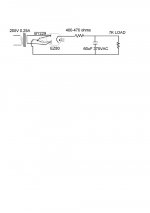
Is this what you mean?
http://www.lundahl.se/hybrid_pow.html
I've used this and it works fine. As with any bridge rectifier, you will have to derate the transformer secondary current to about 60% of the AC current rating.
http://www.lundahl.se/hybrid_pow.html
I've used this and it works fine. As with any bridge rectifier, you will have to derate the transformer secondary current to about 60% of the AC current rating.

jlsem said:
Wow - already. Where did you get your degree so fast?
Well, engineer mind... as near as I can tell.
jamesjung21 said:
To minimise the interaction or cross-talk between the two channels by using two separate PSU, although both channels are sharing single transformer.
...Even though it goes through the same room....whatever....
Oh, I think you need to read my previous thread...
I don't read everything, I would quickly go insane here if I tried


What did you use to provide the activation energy? If a single piece of Magnesium is insufficient, try to ignite more Mag's at once... Don't forget to wear your eye protection !!
Tried arcing with a little MOT modification (20VAC worth of 8AWG) and some pencil leads. Before that I tried heating a can of it amid firebricks, which worked if despite having to get the whole thing a good glow around yellow heat. Don't have any Mg
Tim
Is this correct? Would it work safely if I connect two of these to the single Transfo. ??
Yes that would work just fine. I've used it my preamp and poweramp.
Cheeeeeeers...Yes that would work just fine. I've used it my preamp and poweramp.
Don't have any Mg
How about putting your deeply-plated car Mag wheels?
- Status
- This old topic is closed. If you want to reopen this topic, contact a moderator using the "Report Post" button.
- Home
- Amplifiers
- Tubes / Valves
- Minimal approach with hybrid rectification: Is this possible?