Hi all. I've a pair of 5687 and I want to try to build a preamp loading the tubes with a ccs. Does someone tried to do something like this? Where can I find good ccs shematics for this purpose? And which is the best operating point?
I find this:
http://www.pacifier.com/~gpimm/Active_loads_and_signal_current_control.html
Very interesting approach, particulary the CCS fed shunt regulators! What do you think about this one?
Cheers
Mark
I find this:
http://www.pacifier.com/~gpimm/Active_loads_and_signal_current_control.html
Very interesting approach, particulary the CCS fed shunt regulators! What do you think about this one?
Cheers
Mark
I've used the C4S and Pimm BBMCCS in a number of designs and like them, BUT, they sound very different than R, L or Tx loads and you might not like the sound of them. High end audio is about finding the flavour of sonic presentation you like, and some people like these, and some don't. I'd suggest trying and seeing; they're not really expensive on parts.mark_titano said:Hi all. I've a pair of 5687 and I want to try to build a preamp loading the tubes with a ccs. Does someone tried to do something like this? Where can I find good ccs shematics for this purpose? And which is the best operating point?
I find this:
http://www.pacifier.com/~gpimm/Active_loads_and_signal_current_control.html
Very interesting approach, particulary the CCS fed shunt regulators! What do you think about this one?
Cheers
Mark
CCS fed shunt regs are excellent, and I think I'd have the whole system run this way if I could. I use a superreg in the phono preamps, but ditched the 317 based CCS in the original design and used a BBMCCS. Didn't think there's be much difference, but there was. Also tried the same setup in the front end (drivers) of various poweramps and it was great too. Ditto all of this with the CCS/VR tube regs, but not as quiet as the superreg, though cheaper, and better in poweramps I'd say.
Hi,
For a preamp that's going to be fed mainly by a CDP I'd rather use a 12B4A.
To my ears and mind it's far better suited and doesn't suffer the rather darkish colourations of a 5687 being pretty transparent.
Do have look around at this forum, Brett shared a nice schematic a while ago.
You can of course add a CCS (can't remember if there was one in Brett's design).
Cheers,")
For a preamp that's going to be fed mainly by a CDP I'd rather use a 12B4A.
To my ears and mind it's far better suited and doesn't suffer the rather darkish colourations of a 5687 being pretty transparent.
Do have look around at this forum, Brett shared a nice schematic a while ago.
You can of course add a CCS (can't remember if there was one in Brett's design).
Cheers,
Agree about the 12B4A. My schem has resistive loading, but it wouldn't be hard to modify. Just slap in the CCS and heatsink adequately. A lower B+ would also be possible, say 220-250V.fdegrove said:Hi,
For a preamp that's going to be fed mainly by a CDP I'd rather use a 12B4A.
To my ears and mind it's far better suited and doesn't suffer the rather darkish colourations of a 5687 being pretty transparent.
Do have look around at this forum, Brett shared a nice schematic a while ago.
You can of course add a CCS (can't remember if there was one in Brett's design).
Cheers,
Attachments
I have built several 6SN7's, 5687, 6922, and 12B4 line stages.
In my opinion the 12B4 vastly out performs the 5687. I was happy with my 5687 until I built Brett's 12B4. After building the 12B4 the 5687 has been scrapped.
On the other hand... Frank's 5692 is well worth the effort.
In my opinion the 12B4 vastly out performs the 5687. I was happy with my 5687 until I built Brett's 12B4. After building the 12B4 the 5687 has been scrapped.
On the other hand... Frank's 5692 is well worth the effort.
burnedfingers said:I have built several 6SN7's, 5687, 6922, and 12B4 line stages.
In my opinion the 12B4 vastly out performs the 5687. I was happy with my 5687 until I built Brett's 12B4. After building the 12B4 the 5687 has been scrapped.
On the other hand... Frank's 5692 is well worth the effort.
Thankyou for this suggestion...but I want first try want I've in the drawer...5687,6922,6350 or 6sn7.
For the first one, have someone tried this design in the bottom? I've found it on vacuumstate.
For the power supply I like to try a CCS fed shunt regs, can it be a good idea or not? If not please teach me why

Mark
Attachments
mark_titano said:vacuumstate.
For the power supply I like to try a CCS fed shunt regs
Allen's stuff is superb... the SuperReg shown is a CCS fed shunt reg and is an essential part of the circuit.
You can learn a lot more about this in his Preamp cookbook (an enjoyable read even outside of the audio goodies in it)
dave
planet10 said:
Allen's stuff is superb... the SuperReg shown is a CCS fed shunt reg and is an essential part of the circuit.
You can learn a lot more about this in his Preamp cookbook (an enjoyable read even outside of the audio goodies in it)
dave
Ok, thankyou for the reply.
I want to buy the tubepreamp cookbook but I've got a little problem because I've none credit card ( the only way to pay in online shop...
).Well, I'll try with a simple depletion mode mosfet. Something like this can work well? With the irf 820/830? I can find easily these two mos...
Attachments
![dmmcccs4d[1].gif](/community/data/attachments/47/47924-9697489df9610ba805b60b94191924cc.jpg)
mark_titano said:I want to buy the tubepreamp cookbook but I've got a little problem because I've none credit card ( the only way to pay in online shop...
Just email Allen... i'm sure he can arrange another form of payment... he is just over on the other side of the Alps.
dave
planet10 said:
Just email Allen... i'm sure he can arrange another form of payment... he is just over on the other side of the Alps.
dave
I've did it yesterday...I'll buy a prepaid "reloadable" Poste Italiane card that I can use on visa circuits

http://www.poste.it/en/bancoposta/carte/postepay.shtml
I'm studing the ccs problem...but there are some things I don't undestand:
1) With a standard R load I have to choose the working point that, for the voltage swing I need, minimize the distortion ( that is caused by the non equidistant -Vg curves on the load line). With a ccs the load line is flat...it seems to me a good thing because the distortion is minimal and choose the working point is simpler. But which is the best working point? How have I to choose it?
http://www.machmat.com/sales/kits/fettle/images/ecc83infi.gif
2) How can I calculate the voltage drop trough the ccs? I need an example, so i choose this circuit.
http://www.machmat.com/sales/kits/images/ccscir.gif
I'll try it because is simple and cheep, this is what I need to understand how this thing works: now, if I know the anode voltage how can I find the B+? And if I have the +B how can I find the voltage drop?
Have I to consider the voltage swing that need the next stage? I read it here...
http://www.machmat.com/sales/kits/ccs.htm
Thankyou all for the patience
Mark
Hi Mark
I really do not understand the point about
the flat load line.
At least in a simple circuit like a common
cathode. The CCS replace the anode
resistance. The load line is flat
only if the circuit is unloaded but
when I use my pre amp to feed
an amp the input resistance of the amp
will be the load line of my pre.
The load of a common cathode stage
is the parallel of the CCS with the
actual external load.
Here the CCS isolate from the supply
like a choke but I do not see a flat
load. Yes the load is better because
without CCS it may be little and
a high res. of the load ( light load)
is usually better.
Maybe I'll have a flat load line if my
output direcly feeds the grid of another
tube. So, with the CCS, the first tube is practically
unloaded.
ciao
Federico
mark_titano said:I'm studing the ccs problem...but there are some things I don't undestand:
... But which is the best working point? How have I to choose it?
... How can I calculate the voltage drop trough the ccs?
To choose the operating point, you can do one of two things (or both): spend some time with many Xerox copies of the load lines, a pencil, and a ruler OR build one up with a trimpot to adjust the current and start measuring.
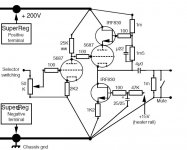
The voltage drop should be whatever you're going to swing as output plus the minimum voltage that the CCS needs to work. In the case of the little two transistor cascode job I wired up yesterday for a 6SN7 plate load, I wanted to swing about 30 volts up and down, and the current source needed about 10 volts of its own. The cathode circuit biased the tube with about 3.5V cathode-to-grid. At my desired current (8 ma), the tube curves showed that I'd have about 160V on the plate at that current. Add the 30 volts of swing, the 10V to sustain the CCS and I end up needing a 200V supply. More is OK as long as the transistors don't exceed their ratings.
fscarpa58 said:Hi Mark
I really do not understand the point about
the flat load line.
At least in a simple circuit like a common
cathode. The CCS replace the anode
resistance. The load line is flat
only if the circuit is unloaded but
when I use my pre amp to feed
an amp the input resistance of the amp
will be the load line of my pre.
The load of a common cathode stage
is the parallel of the CCS with the
actual external load.
Here the CCS isolate from the supply
like a choke but I do not see a flat
load. Yes the load is better because
without CCS it may be little and
a high res. of the load ( light load)
is usually better.
Maybe I'll have a flat load line if my
output direcly feeds the grid of another
tube. So, with the CCS, the first tube is practically
unloaded.
ciao
Federico
Ciao Federico
Maybe I don't understand the point about the flat load line, at all. Now my question is: If I'm going to choose the working point of a simple pre that use only half of a double triode ( 6sn7, ecc88, 5687 o something else) with a ccs load,which curves I have to use? Have I to choose the working point thinking that the load of a common cathode stage is the parallel of the CCS with an external load? Maybe what you did not understand is that I don't consider this point
 I have a lot to learn. what I thought is that, if the current is constant, a voltage swing in the grid can cause only a voltage swing on the anode, so the load line is flat. Gary pimm helped me to thinking it...
http://home.pacifier.com/~gpimm/Active_loads_and_signal_current_control.html
Well...I'm a little bit confused
Mark
SY said:
To choose the operating point, you can do one of two things (or both): spend some time with many Xerox copies of the load lines, a pencil, and a ruler OR build one up with a trimpot to adjust the current and start measuring.
The voltage drop should be whatever you're going to swing as output plus the minimum voltage that the CCS needs to work. In the case of the little two transistor cascode job I wired up yesterday for a 6SN7 plate load, I wanted to swing about 30 volts up and down, and the current source needed about 10 volts of its own. The cathode circuit biased the tube with about 3.5V cathode-to-grid. At my desired current (8 ma), the tube curves showed that I'd have about 160V on the plate at that current. Add the 30 volts of swing, the 10V to sustain the CCS and I end up needing a 200V supply. More is OK as long as the transistors don't exceed their ratings.
Thankyou Sy. Can you post the circuit? Maybe I can undestand it better...

Mark
Here's the circuit I used. Note that this if for test jig purposes (where it worked quite well!), not for actual use in my audio system. My motivation was to extend some of Morgan Jones's excellent analyses to a few new tube types. Parts choice was only loosely tied to optimization- basically, I used what I had on hand.
Attachments
Mark, re the loadlines question, the anode load (whether R, L or CCS) and the input impedance of the following stage are in parallel. So for example if you had an 8k resistor for the anode load and the grid resistor for the following stage is 100k, then the effective load seen by the tube, and what you should actually plot as the loadline is 8k//100k = 7407R
Now because a CCS (should) have a very high resistance, say 10M, and the following grid resistor is still 100k, the effective load is 10M//100k = 99k. If the impedance of the CCS is even higher such as the Pimm designs, then you get closer and closer to only the grid resistance of the following stage, so as a shorthand, people say the loadline is flat.
With all the tubes you listed below, a CCS load on the anode and any sort of normal load from the following stage, a flat loadline drawn on the curves will very closely approximate what's actually going to go on in the circuit. If you want to be really anal about it, plot the resistance of the following stage. But it won't make much of a difference unless it's really low.
- Status
- This old topic is closed. If you want to reopen this topic, contact a moderator using the "Report Post" button.
- Home
- Amplifiers
- Tubes / Valves
- 5687 and ccs?