All,
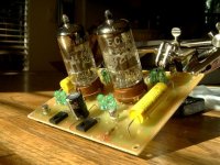
Playing around with a C4S'ed Bottlehead Foreplay clone using 6GM8 low voltage dual triodes on a PCB. Thinking will use either a 24V or 30V B+ (max plate voltage rating). Anyone have any thoughts on a recommended operating point for this tube?
Thank you -ALBQ
Playing around with a C4S'ed Bottlehead Foreplay clone using 6GM8 low voltage dual triodes on a PCB. Thinking will use either a 24V or 30V B+ (max plate voltage rating). Anyone have any thoughts on a recommended operating point for this tube?
Thank you -ALBQ
Attachments
Hello,
I've used the ECC86 in a CDP output at 3 mA / 15 Va-k. Works fine, maybe a bit on the smooth side sound-wise (which is usually a good thing).
I would try 3 mA / 25Va-k. So, in a Foreplay circuit, set both CCSs to 3 mA, use a 330 ohm cathode resistor (unbypassed) on the input tube's cathode, and use 50V B+.
Check that plate voltage at the input tube is ca 25V (20-30V) after warmup. Grid stoppers - say 1k on input and 10k on cathode follower - might be a good idea.
Ground the internal shield (pin 9).
If you use AC heating, make sure to balance the feed with 100-ohm resistors. I would also raise the heater to 10-15Vdc, with cap bypass to ground.
Good luck,
6gm8 (ecc86) Bias Point.
The circuit I'm using has +/- 22V supply rails. Its a cathode follower, with a CCS connected to the cathode.
Its a line level preamp, with the expectation driving a power amp with a 100 K input impedance.
I tried 3 different methods trying to figure a good bias point for a 6gm8
1) A load line was plotted on the plate curves, provided by a Philips data sheet.
Using a CSS the load line is horizontal - however, the 100 K load should also be included.
This adds a slight tilt to the load line.
After some measurement on the plate curves, Vgc ~ -0.37 V looks good, with I = 3.4 mA
2) I have have my home made RC signal generator which creates an e shaped waveform.
The input and output waveforms were compared.
Couldn't see much, if any difference, between the 2 waveforms, changing the bias current from 3 mA to 4.9 mA.
3) A complete system was connected and listened to :
CD player ==> 6gm8 line level preamp ==> MOSFET chip amp ==> B&W 110's.
Music was Beethoven Piano Concerto No. 5, second movement (Lief Oves Andsnes)
and Dave Brubeck - Time Out.
A trimmer pot was adjusted without knowing what the bias was.
However, the bias was kept between 3.0 mA and 4.9 mA
After quite a number of listening sessions - finally settled on Vgc = -0.39V
Measured the resistor value, and calculated the bias current, which worked out to be 3.4 mA
So driving a power amp with a Zin = 100 K ,
I'd say X marks the spot when Vgc ~ -0.375 and I = 3.4 mA
.
- Status
- This old topic is closed. If you want to reopen this topic, contact a moderator using the "Report Post" button.
