i want to see if i can swop the solid state pre amp in a pa amp to a tube pre amp for guitar work, but i dont know if the power supply would hold it, i cant see any markings apart from 130v 0.3a, 6.3v 3.5a, and 6.3v 0.7a
now i assume the 130v 0.3a powers the tubes
the 6.3v 3.5a goes to the tubes so is probly heater power
the 6.3v 0.7a goes through a rectifier to the s.s. pre amps, a simple pair of discrete transistors by the way, of witch there are three, mic 1, mic2, and aux.
Aux works fine for line level input from a cd player, and mic is low impedeance (600ohm) microphone.
there are 4 el84 tubes and one 6a08? poss 6aq8, cant read too well, the printing isnt to great.
do you think the power supply would hold up with another tube for the pre amp? thanks for the help so far, see you later, steve.. ..
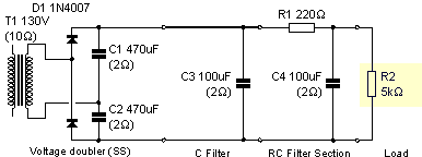
psychosteve said:ok call me stupid if you want, but, full wave doubler???
Greg means a voltage doubler something like the one below i think. Ignore the component values.
Attachments
why?
i know i dont know much about tube design, but if the tubes ive got work well how they are wired up,
why not use the same for another tube to use as a pre amp? is the voltage doubler aplicable for all the tubes?
and if so would i not be better off using a different transformer?
and would it improve the sound or give me more power?
sorry audiousername the pic doesnt come up, so i cant see it exept as thumb nail.
psychosteve,
I'm not sure why Greg suggested a voltage doubler, apart from wanting to get more voltage?
Seriously, 130V ain't much, though it definitely can be made to work. Well, as you say, it's working now.
It seems like he was thinking of getting a higher voltage for the small-signal valves and leaving the lower voltage for the EL84s. Perhaps wait for him to post what he had in mind. I would have made some suggestions but it's past midnight here and I'm sleepy
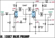
The 100K load resistors are the plate load resistors for the 12AX7 sections. Valves are transconductance devices. A change in their grid voltage produces a change in the plate current. This change in current is developed across the plate load resistor (the 100K resistor). Lowering its value reduces gain (and usually increases distortion), removing it makes the circuit basically useless. 'night
130V sounds way low for a EL84 amp. Can you take some measurements of the voltage after the rectifier or on the plates of the EL84s (being a noob PLEASE follow safety guides ) and post them for us? For guitar I would want around 300V on the EL84s. The current sounds like more than enough, You could run three or four 12AX7s in the preamp and make a real screamer.
) and post them for us? For guitar I would want around 300V on the EL84s. The current sounds like more than enough, You could run three or four 12AX7s in the preamp and make a real screamer.audiousername said:I'm not sure why Greg suggested a voltage doubler, apart from wanting to get more voltage?
Yup!
Those tubes will be happier at +260V (loaded) than +130
I would imagine you have heaps of spare current. A 12AX7 only uses a couple of mA.
The best thing to do is look at the HV can capacitors, there will be one that has a wire going to the output transformer centre tap.
Measure the voltage from this point to ground (Please read the safety thread
If it is about 300V or so, just whack a 10K resistor to a 10uF capacitor and theres your B+.
What you should do is remove the SS preamp section and use the 6VDC to power the tube filament (DC is nice and quiet!) Get those transistors out of there!
I would copy a Fender input stage and put a pot on the output You might want to read this thread
SHiFTY,
I imagine Steve already read that thread. He posted the SC valve preamp schematic!
Steve,
As Tim has said, measurement of the B+ would be useful. Thinking it over, it is possible you may already have a voltage doubler in there. 130V is quite low. A schematic would be even better if you have one!
EDIT: my turn to post when it's past midnight in England... lol
I imagine Steve already read that thread. He posted the SC valve preamp schematic!
Steve,
As Tim has said, measurement of the B+ would be useful. Thinking it over, it is possible you may already have a voltage doubler in there. 130V is quite low. A schematic would be even better if you have one!
EDIT: my turn to post when it's past midnight in England
... lollaugh, yup.
ok i tryed measuring and yes i got 269v
i looked at all the components and was amased at how simple iut all was, THEN i looked at the transformer, on the reverse where i couldnt see till i took it out was the primary windings, rated at............... 115v ac, the case says 220-250v the plug and fuse are rated to 240v nominal. so i guess i aint got HALF?????? the amps i thought. are the heaters supposed to be conected ac? the tap from the transformer goes strait to the tubes, so its 12.6v 1.75a AC
if this holds true (2 x volt = 1/2 amps) then tube power is 260v 0.15a. DC, it goes through a 2 diode bridge to a series conected pair of 200mf 180v caps.
is this still enough to run another tube?
would i get better performance upgrading to a full bridge rectifier and some higher rated caps, i got some samsung 400uf 400v caps that i could parallel to give 800uf. better smoothing, more reserve of power???
P.S. i dont have the schem for the amp, its an
"Eagle international, PA935n, hybrid public address amplifier."
if you can find one id be gratefull, but i havnt managed yet. cheers for the help guys, steve.. ..
ps, yes ive read the safety guide lines, my dad was a sparky anyway so im quite good with electics.
"Eagle international, PA935n, hybrid public address amplifier."
if you can find one id be gratefull, but i havnt managed yet. cheers for the help guys, steve.. ..
ps, yes ive read the safety guide lines, my dad was a sparky anyway so im quite good with electics.
psychosteve said:apart from the isolation factor, is there any reason to use a transformer at all????? why not use 240vac strait to the bridge/cap?
BECAUSE IT WILL KILL YOU!
That's why. In the UK mains neutral is connected to earth. If you put a bridge rectifier on the mains, the output will be alternately connected directly to the live then to the neutral. You then bond the 0V of the supply to the chassis and the chassis is alternately at live or neutral. Plug it into something (if it hasn't already killed you) and if that something is earthed, there will be an almighty flash and a bang.
Let's hear no more about not using mains transformers. We need our membership!
I KNOW IT WOULD KILL YOU!!!!!
and i did say apart from the isolation issue,
its just that ive got some 2kw current ballance isolation torroids that where custom made for a huge micro wave generator. they are real high spec, military stuff, and 30mm accross 20mm high, and handle 2kw at 410volt. an was wondering if any step up/down was actualy needed to run tubes if the recomended voltage seems to be 260v
im not going to go plugging stuff strait to the mains without some issolation. thanks for the warning though, and i should have made myself clear for those who are not aware of the saftey issues, cheers bud, steve.. ..
 Even if you knew what you were about (and it wasn't clear at the time whether you did), other people read these threads, so it's important not to accidentally lead someone into something dangerous.
 150ma will work (I've run 3-12AX7 2-EL84 off of 90ma with a 5Y3GT rectifier). If any change to the caps, I would lower them to around 40Mfd in a guitar amp. The big caps may give you better bass but will sound to "tight", Who knows you may like it that way. You could try a full wave bridge to up the voltage, remember to lift the secondary center tap for this. In the long run it may be easier to get a different power transformer.
- Status
- This old topic is closed. If you want to reopen this topic, contact a moderator using the "Report Post" button.
- Home
- Amplifiers
- Tubes / Valves
- help for tube noob