Please help.
Recently constructed OTL amp from Glass Audio magazine and have some problems with it. I use 6 (6AS7) per channel and everything else is the same as published in the magazine. Amp is working fine with 4 ohm and 8 ohm load but very unstable with 16 ohm load. Very unstable means dc fluctuation on the output aprox. 1 Hz rate .I am seeing that on 8 ohm load too but on higher power output.
Any help will be appreciated.
Thanks.
P.S. Here some pics. from construction
Attachments
Hi,
It seems to me there's simply a DC offset on the output.
A small amount of that is pretty normal and harmless.
This may be due to a inblance in the biasing of the output valves where one bank draws more current then the other or there's a leaky couplingcap somewhere downstream.
Other than that I see no particular reason for instablility into a 16 Ohm load per se, it's probably just more obvious.
Cheers,")
Very unstable means dc fluctuation on the output aprox. 1 Hz rate .I am seeing that on 8 ohm load too but on higher power output.
It seems to me there's simply a DC offset on the output.
A small amount of that is pretty normal and harmless.
This may be due to a inblance in the biasing of the output valves where one bank draws more current then the other or there's a leaky couplingcap somewhere downstream.
Other than that I see no particular reason for instablility into a 16 Ohm load per se, it's probably just more obvious.
Cheers,
Sounds like motorboating to me. It's usually caused by coupling through the power supply. The reason it only shows up on a 16 Ohm load is that the 16 Ohm load doesn't load the amplifier as heavily, so it has a little more gain, and if its stability is marginal, that's enough to start oscillation.
There are two ways of curing motorboating:
You attack the symptoms and reduce the audio coupling capacitors to half or a quarter their original value.
You attack the problem and regulate the HT to the driver stages.
By the way, I couldn't see a connection from the earth pin of the mains IEC to the chassis of the amplifier...
Thanks for help.
DC offset is less then 100mV on 4 and 8 ohm load.
DC fluctuation on 16 ohm load is +/- 5v or more.
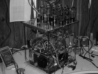
Picture shows construction detail. Amp is ready and all grounds are connected.
Yesterday I spoke with Mr. Rozenblit who designs this amp and looks like this is normal for this amp.
I tried to lower feedback and that help a lot but hum level rises up to unacceptable level. Seems to me that I need regulated +/- 150 V supply.
DC offset is less then 100mV on 4 and 8 ohm load.
DC fluctuation on 16 ohm load is +/- 5v or more.
Picture shows construction detail. Amp is ready and all grounds are connected.
Yesterday I spoke with Mr. Rozenblit who designs this amp and looks like this is normal for this amp.
I tried to lower feedback and that help a lot but hum level rises up to unacceptable level. Seems to me that I need regulated +/- 150 V supply.
Hi,
By the same token output impedance will rise as well...
Yet, as you added two extra output valves you may get away with lowering overall feedback a little although to my mind that's really not the solution.
I wonder why and I also wonder how you'd manage to achieve that.
Personally I've built these amps as monoblocks using 8 output valves and it didn't cause any trouble. DC offset was never more than 5-25 mV with selected valves.
Since the driver stages are already regulated I'd suspect the coupling caps.
Are you sure you didn't put in a faulty one? Or ones with a much higher than intended value perhaps?
Cheers,
I tried to lower feedback and that help a lot but hum level rises up to unacceptable level.
By the same token output impedance will rise as well...
Yet, as you added two extra output valves you may get away with lowering overall feedback a little although to my mind that's really not the solution.
Seems to me that I need regulated +/- 150 V supply.
I wonder why and I also wonder how you'd manage to achieve that.
Personally I've built these amps as monoblocks using 8 output valves and it didn't cause any trouble. DC offset was never more than 5-25 mV with selected valves.
Since the driver stages are already regulated I'd suspect the coupling caps.
Are you sure you didn't put in a faulty one? Or ones with a much higher than intended value perhaps?
Cheers,
Maybe as an alternative to lowering coupling cap values, you can beef up supply cap values? Frank's suggestion of a defective coupling cap (or possibly a bad resistor?) seem to be possibilities if only the output stage is not regulated. Is the grounding *really* solid on this amp to all components related to signal paths?
Btw, I recently replaced the offset and bias adjustment circuits on my DC coupled OTL, extending the potentiometer shafts out the back of the chassis & including adding a bias monitor test point also to the back of the chassis. This was occasioned by the inaccessibility of these pots before, as well as the high -500V dc potential they were at. Easy to catch a lethal jolt if not careful. Now, they're insulated by a 3/8" thick piece of polycarbonate from the chassis, and their shafts are extended by 3" long pieces of polycarbonate 1/4" rod with 1/2" polycarbonate coupling sleeves to the potentiometer shafts.
I found that, with a little care, it is possible to drill and tap 6-32 holes right through a 1/4" (6mm) metal potentiometer shaft, making it straightforward to add plastic couplers and shaft extensions to them.
I found an interesting way to damp tube microphonics on this OTL, and gain a bit of shielding and heat sinking in the process. i bought a sheet of .025" dia wire dead soft aluminum wire fabric with about a 70% open ratio, cutting 'x's' where the tubes were to pass through, pre-forming the wire cloth and then fitting over the tube bulbs at the mid points to near the top. Much of the mechanical damping effect is by loosely coupling the tubes. This has markedly improved the resistance to microphonics of the DC coupled OTL's tubes, although it doesn't do much for the visual aesthetics!
Btw, fdegrove - you ever hear of anybody trying wire mesh as a tube dampener?
It really made a difference with my OTL. I had just installed the new bias & offset circuits & had it hooked to my 101db/w/m Basement blasters. For some reason that I forget, I tapped one of the 6as7g's and could readily hear it through the speaker as well as at the tube locally. So I thought 'That has to be affecting the sound at high SPLs.' which was exactly how I was running the OTL right up to & sometimes past clipping between two of these highly efficient speakers there had to be 115db SPLs or even more at the OTL. So, I tried jamming some fiberglass insulation between the OTL tubes - big improvement in imaging but I wasn't doing the OTL any favors wrt dissipating heat - so I eventually thought of the wire fabric idea which seems to work comparably well, but with no downside wrt heat dissipation or convective air flow. The chassis could still stand some additional dampening, btw, even with this mod.
The results aren't all in yet since I haven't run the OTL on my best equipment, but the tube damping gives an impression of rock solid imaging at all dynamic levels and much enhanced microdetail capability even at ear bleed levels, if the source is good enough.
Hi,
Not in the same you applied it but when you look at some older screening cans you'll easily see the resemblance with a mesh
structure when the inner wrap is unfolded.
Granted these were only used on 7 and 9 pin small signal tubes but the basic idea is pretty similar.
There were also these things called "tubesox" or something similar that were composed of a cylindrical kevlar weace that was supposed to be slid around the tube to reduce microphony.
Fortunately for me my OTLs don't seem to suffer from microphony at all but damping in general helps a great deal to improve image focus.
Same way a better damped speaker cabinet would reduce cabinet colourations, etc.
Cheers,
Btw, fdegrove - you ever hear of anybody trying wire mesh as a tube dampener?
Not in the same you applied it but when you look at some older screening cans you'll easily see the resemblance with a mesh
structure when the inner wrap is unfolded.
Granted these were only used on 7 and 9 pin small signal tubes but the basic idea is pretty similar.
There were also these things called "tubesox" or something similar that were composed of a cylindrical kevlar weace that was supposed to be slid around the tube to reduce microphony.
Fortunately for me my OTLs don't seem to suffer from microphony at all but damping in general helps a great deal to improve image focus.
Same way a better damped speaker cabinet would reduce cabinet colourations, etc.
Cheers,
Hi.
I don’t think this problem is related to tube microphony. I run tests with resistive load.
In my opinion I think that ground is OK.I use star configuration. Center point is on filter capacitors (8x1100uFD/200v) see pictures.
Coupling caps are: C3 3mFd instead 2.2uF and C4/C5 0.2uF instead 0.1uF.
Last night I cerate simple web site with some pictures.
Here it is:
http://marioaudio.freewebspace.com/
Thanks again for suggestions.
Mario
You might try going to the exact values in the original schematic. When you have that many caps within a global feedback loop, you have to stagger their respective time constants to avoid the risk of motorboating which will get worse with increasing open loop gain especially under light reactive load. This will occur because the open loop low frequency phase shift under these conditions may reach 180 degrees at some low frequency where there is still feedback reduced open loop gain causing low frequency oscillation.
I just tacked on a comment or two about microphony with the 6as7g in my last post. Nothing to do with your situation.
I just tacked on a comment or two about microphony with the 6as7g in my last post. Nothing to do with your situation.
- Status
- This old topic is closed. If you want to reopen this topic, contact a moderator using the "Report Post" button.
- Home
- Amplifiers
- Tubes / Valves
- OTL amp help