Since I’ll rebuild my amp because I have some hum problems (if you’d like to see what happened go over here ), I’d like to start a new thread to ask some questions to develop the schem.
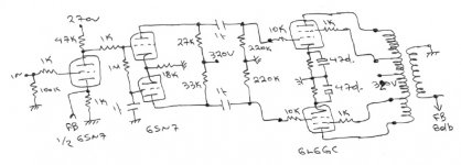
The bias of 6L6GC is 320V at about 70mA.
1) If you believe that I must change any value of the components for better results, please tell me which one to change.
2) Instead of using 6SN7 as an input tube, do you believe it’s better to use a single triode driver? I read somewhere that this tube doesn’t have internal screening and this may compromise channel separation.
3) Is it better to use bypass cap at the first stage or to leave it as it is?
Thanks
")
The bias of 6L6GC is 320V at about 70mA.
1) If you believe that I must change any value of the components for better results, please tell me which one to change.
2) Instead of using 6SN7 as an input tube, do you believe it’s better to use a single triode driver? I read somewhere that this tube doesn’t have internal screening and this may compromise channel separation.
3) Is it better to use bypass cap at the first stage or to leave it as it is?
Thanks
Attachments
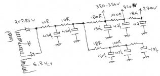
Too much C in the PSU, use a choke instead. But that's not going to cause hum unless the current spikes are drawn in via ground loop.
I don't like star grounding. Too damn messy. Just ground the first stage (which should be a 6SL7, you'll have way too little gain as-is) to the input jack, then connect those to the rest of the grounds however you please.
Tim
I don't like star grounding. Too damn messy. Just ground the first stage (which should be a 6SL7, you'll have way too little gain as-is) to the input jack, then connect those to the rest of the grounds however you please.
Tim
Where is the problem with that?Too much C in the PSU, use a choke instead.
I prefer not to use chokes!More ringing problems!
So,there's no any problem to use each half at each channel?Geez, it's going into the same damn room, you WON'T notice 2pF of crosstalk.
I'm planning to use about 8dB of FB.I think I'm fine with only one half of 6SN7.A Mu of 70 (6SL7) is too much for my purpose.You need more gain because you need to remove as much with NFB to get it to sound good.
I think so.That's why I'm asking.Please give me a more clearly explanation.
You want more than 8 dB of feedback. At that low level, the THD does decrease, but third and higher actually increase over the open loop condition. 15-20 dB is probably more appropriate.
I don't get the ringing comment. I think the cap situation you show is OK, but a choke at the first pi filter would help efficiency and knock down hum quite nicely.
I don't get the ringing comment. I think the cap situation you show is OK, but a choke at the first pi filter would help efficiency and knock down hum quite nicely.
Since I use PSUDII for my PSU designs I don't like to use chokes.I can't design easilly a stable and not ringing PSU.With caps and Shindo style,things are better.Chokes are more expensive,too.I don't get the ringing comment. I think the cap situation you show is OK, but a choke at the first pi filter would help efficiency and knock down hum quite nicely.
So, I must change the first tube?15-20 dB is probably more appropriate.
Use 6SL7 as sch3emat1c said or to parallel the two halves of 6SN7?I prefer the last one cause I allready have the tubes and I also can make the two channels identical.
With a C-input filter, I don't see any ringing in any of the amps I have on hand. That's not the same as a simulation, granted, but has its virtues. L-input filters will respond nicely to snubbing, but that's not an issue here.
Paralleled 6SN7 will not give you enough gain- you don't increase mu, you just drop rp. Use the 6SL7.
Paralleled 6SN7 will not give you enough gain- you don't increase mu, you just drop rp. Use the 6SL7.
Ooops...yes, gain doesn’t increase.Paralleled 6SN7 will not give you enough gain- you don't increase mu, you just drop rp. Use the 6SL7.
Is there any single triode that I can use at the place of 6SL7??
If I’ll use 6SL7.Can you help me with the bias? Which is the best bias point for this tube?
I think there is a single version of the 6SL7, I just don't remember what it is. But there's no reason whatever to use it- the section-to-section coupling is negligible at any reasonable frequency. I think it's less than half a picofard Cp-p.
The 6SL7 likes to run at about 1.2-1.5 ma with most reasonable plate voltages.
The 6SL7 likes to run at about 1.2-1.5 ma with most reasonable plate voltages.
I'll go with 6SL7!
What do you say about my third question?Bypass the first stage or not?
About FDB...
I hear everywhere different opinions.It depends on schem or 15-20 dB is the best amount?
Some diy-ers say not to go over 10dB!
hmmmm...I remember a friend of mine who tried different amounts of FDB, a few days ago and he liked the sound of his amp at about 15dB!
You can try whatever you want but you'll most likely be happy with either very little (or none), most likely with a triode output, or a whole lot (20dB or so typical), most likely with a pentode output. UL could go either way but I'd suspect more.
And besides, if you choose less NFB, that's why GOT made volume controls.
Tim
And besides, if you choose less NFB, that's why GOT made volume controls.
Tim
Hey sc3mat1c
From yesterday it sticked in my head an idea to use a switch.So,I can choose everytime I want triode,UL or tetrode!
But everytime, I need another amount of FDB right?So,another switch for this,too.
What do you say about this?
I don't like four switches,though.
UL needs more than 20dB?
From yesterday it sticked in my head an idea to use a switch.So,I can choose everytime I want triode,UL or tetrode!
But everytime, I need another amount of FDB right?So,another switch for this,too.
What do you say about this?
I don't like four switches,though.
UL could go either way but I'd suspect more.
UL needs more than 20dB?Er, the larger figure, not necessarily more than 20dB. My bad wording...
If you want to switch, then instead of injecting NFB through a cathode resistor on the first stage as is usually done, use a 100 ohm (or whatever) potentiometer instead of a fixed one. Mind that gain will go up dramatically as NFB is reduced.
Tim
If you want to switch, then instead of injecting NFB through a cathode resistor on the first stage as is usually done, use a 100 ohm (or whatever) potentiometer instead of a fixed one. Mind that gain will go up dramatically as NFB is reduced.
Tim
resident said:About 6SL7,I'd like to ask some questions.
What do you say to bias it with
Va=280V
Ra=80-100K
Rk=1K
And bypass Rk or not?
Have you tried laying out the load lines for this on the Ip vs Vp curves for the tube? It's easiest if you start with the idea that Rk will be bypassed, and see where that takes you with respect to swing and distortion.
As a newbie I'm not going well with curves.
I found out my values by laying out a loadline and yours suggestion to keep 6SL7s current at 1,2-1,5mA.
I cann't change Va,though.It'll be around 280-300V.As my anode voltage on 6L6 will be around 320-350V.
As I see my loadline on curves, with 80K anode load and around Rk=1K I have Ia around 1,2-1,5mA and minimum distortion.Am I right or not?
Maybe, I must read some books on this.
- Status
- This old topic is closed. If you want to reopen this topic, contact a moderator using the "Report Post" button.
- Home
- Amplifiers
- Tubes / Valves
- advice for 6L6GC P-P amp