hello everybody,
i wanna build an amp : an push pull el84; that is also driven by an el84
the problem is that i have already material lying around.
i have a power supply that if you put 220 on it (i live in europe) you get 140 volt out of it. (0.2amp)
the orginal design was an push pull el84 driven by 3 ecc83, and also 2*ecc83 for the phono stage.
i will have to put an extra trannie for the heaters.
but now the real problem, i 'm gonna go solid state psu, because it's a first project, and also wanna keep the cost low. In the original there is a voltage doubler (the one you get with the psu designer, hahaha, it uses 100uf) , so it puts out 280 volt, that's allright, (i has to be 300 but i don't think i can get that, or am i wrong, still with 280 i gotta work also).
but what after that voltage doubler ? a snubber circuit, and an CRC or CLC circuit and how to implement ?
i find psu schemes the hardest of an amplifier, that's why i call the help of some guys. i have already simulated with the psu designer, but don't feel to sure about it. so any help is welcome
thanx guys
")
Hi then_dude,
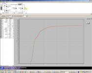
If I were you, I would go something like that (see attached file). This sim was quick and I don't know much about your PP setup, voltages and so on. I assumed 0.1 A per channel / one psu. However with 1 xformer per channel this does not give you much room for output power and might be insufficient.
(PSUD2, accuracy=high, f=50Hz, Ui=240V, offload Vo=140V)
Attachments
Play around with the transformer -- if you have the nerve you can use a spare filament transformer to place 12.6VAC onthe 6.3VAC winding -- this will double the voltage on the HV secondary (of course, you disconnect the original primary connections );!
a doubler works fine for tube devices -- very suitable for regulation, the displayed image is a regulator with an LM317 regulator which has its adjust pin lifted by a zener string (courtesy of National Semiconductor)
a doubler works fine for tube devices -- very suitable for regulation, the displayed image is a regulator with an LM317 regulator which has its adjust pin lifted by a zener string (courtesy of National Semiconductor)
An externally hosted image should be here but it was not working when we last tested it.
- Status
- This old topic is closed. If you want to reopen this topic, contact a moderator using the "Report Post" button.