there's something that's nagging me regarding current flow in the below schematic.
i am of the opinion that total current drawn will flow thru R2, before splitting off to the left where the choke is and thru R1.
ie, if 60mA is total current drawn by 300b and 10mA is drawn by driver,
R2 will have 60mA flowing through and R1 will have 50mA flowing thru, with 10mA flowing to the choke.
or it it the other way around where R1 will have 60mA flowing thru and R2 will have 50mA, with the 10mA flowing to the choke?
An externally hosted image should be here but it was not working when we last tested it.
i am of the opinion that total current drawn will flow thru R2, before splitting off to the left where the choke is and thru R1.
ie, if 60mA is total current drawn by 300b and 10mA is drawn by driver,
R2 will have 60mA flowing through and R1 will have 50mA flowing thru, with 10mA flowing to the choke.
or it it the other way around where R1 will have 60mA flowing thru and R2 will have 50mA, with the 10mA flowing to the choke?
Some comments
1st I don't believe that the circuit is practical but lets look at it and answer your questions anyway.
The entire bias for the 300B must be developed across R1.
The driver tube current must also flow through the 300B.
R1 will have the total current through it and that current will split
- some (50mA using your values) to 0v via R2
- some (10mA using your values) to 0V via the Driver tube and R3
The driver tube will have only the voltage developed across R2 at its anode to operate from.
In its favour I believe that you would get some form of bootstrap action to assist in signal swing to the300B grid as a result of the choke connection to the R1/R2 node (low impedance signal source) and that the driver tube would therefore be running in an almost constant current mode as a result of the bootstrap action.
Maybe it just more clever than it appears at first glance and will work after all.
Any other takers to correct my or garbages miss-conceptions.
Cheers,
Ian
DRD Circuit
I believe the circuit garbage posted was the DRD circuit offered by Welborne Labs? http://www.welbornelabs.com/drd.htm
Anyway, it's probably easier to think of the current flow in terms of conventional current (i.e. from + to -) here. The current flows from the B+, through the OPT and 300B and R1. Here the current splits, passing through the choke to the driver tube (I think it's a 6N1P...) and the 300B grid while the remainder is passed to ground through R2.
Thus the bias for the 300B is developed by the combined voltage drop across R1 and the DC resistance of the choke (which would not be negligible since the choke is probably >30H)
I'm rather new at this, so don't take my word as gospel...
The circuit (except for the "Ultrapath" connection - i.e. the oil cap) is similar to Jeremy Epstein's "Free Lunch" direct coupled amplifier. http://home.earthlink.net/~jeremyepstein/freelunch.html He has documented this quite well and explains with example how to change the operating point
Re: DRD Circuit
yes, this is the Vaccum Tube Valley DRD circuit that is used by wellborne labs.
i actually had a drd calculator to calculate the resistor chain at this thread.
the reason why i'm asking about the current directions is because someone asked in AA, about how to size the resistor. so i pointed him to that calculator.
but seems like we have different opinions as to how the current should flow.
i thought that R2 will have 60mA flowing through and R1 will have 50mA flowing thru, with 10mA flowing to the choke.
the direction of current flow will determine resistor sizes in the DRD resistor chain.
if i made a mistake, i would like to correct the drd calculator so that in future, people wanting to build this circuit can benefit from the calculator.
as of now, there are a opposing camps of thoughts. would someone kindly confirm the current flow?
thanks.
cheers,
garbage
Guido Tent said:Hi,
No bootstrapping as the AC current is shorted ("oil") directly across the cathode of the 300b.......
neat circuit !
regards
audiousername said:I believe the circuit garbage posted was the DRD circuit offered by Welborne Labs? http://www.welbornelabs.com/drd.htm
yes, this is the Vaccum Tube Valley DRD circuit that is used by wellborne labs.
i actually had a drd calculator to calculate the resistor chain at this thread.
the reason why i'm asking about the current directions is because someone asked in AA, about how to size the resistor. so i pointed him to that calculator.
but seems like we have different opinions as to how the current should flow.
i thought that R2 will have 60mA flowing through and R1 will have 50mA flowing thru, with 10mA flowing to the choke.
the direction of current flow will determine resistor sizes in the DRD resistor chain.
if i made a mistake, i would like to correct the drd calculator so that in future, people wanting to build this circuit can benefit from the calculator.
as of now, there are a opposing camps of thoughts. would someone kindly confirm the current flow?
thanks.
cheers,
garbage
current
In DC terms
If 60mA is drawn by the 300B the maximum current anywhere in the circuit is 60mA because the 300B is the only connection to B+
R1 is connected to its cathode so the full 60mA flows through it
10mA is drawn into the driver tube through the choke, so the remaining 50mA flows to earth through R2.
Is the above right? or have I lost my brain.... did a 3 hour English exam this morning... eep

thanks for the replies guys. ")
Federico, thanks for the circuit. it clears up my doubts regarding the current flows.
however, some questions...
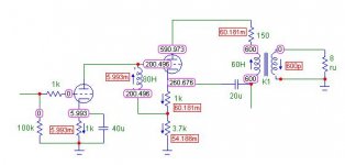
i noticed that your 80H choke did not contribute any voltage drop in your circuit. also, the OPT did not have voltage drop.
have the above circuit been built yet?
if so, have you experimented with values other than 20uF for the ultrapath cap?
thanks a lot.
rgds
garbage
Federico, thanks for the circuit. it clears up my doubts regarding the current flows.
however, some questions...
i noticed that your 80H choke did not contribute any voltage drop in your circuit. also, the OPT did not have voltage drop.
have the above circuit been built yet?
if so, have you experimented with values other than 20uF for the ultrapath cap?
thanks a lot.
rgds
garbage
hi garbage
excuse me for the confusion.
I only simulate it to clarify things about
current flows. It does not exist, really.
I forgot the choke resitance, while I put
150 Ohm in serie to the OPT to take
count of primary resistance.
I tried some values other than 20u
but without improvements of
freq. response. Maybe other influences
like output res ( as a function of freq.) etc.
I only spent five minutes on it after
reading your interesting post.
If yuo want, I can do some investigation.
I am speaking about simulations obviouly.
bye
Federico
oic.
Federico, no worries then.
btw, i've updated the drd calculator. if you are interested, you can take a look at it. posting of drd calculator
cheers
garbage
Federico, no worries then.
btw, i've updated the drd calculator. if you are interested, you can take a look at it. posting of drd calculator
cheers
garbage
Just think of it as the choke/driver/R3 is parallel with R2. I think the fact that it is drawn up and over rather than heading straight to ground is confusing. The confused approach was assuming current flowing up through R3 and the driver, then back to ground through the choke and R2. Nice trick. If we could only sample some of that ground to ground current, we could save on the electric bill.
Move the driver tube lower on the drawing so the branch through the choke aims downward and it becomes clearer. The power tube grid connection doesn't enter into the current flow question.
Move the driver tube lower on the drawing so the branch through the choke aims downward and it becomes clearer. The power tube grid connection doesn't enter into the current flow question.
Enzo said:Just think of it as the choke/driver/R3 is parallel with R2. I think the fact that it is drawn up and over rather than heading straight to ground is confusing. The confused approach was assuming current flowing up through R3 and the driver, then back to ground through the choke and R2. Nice trick. If we could only sample some of that ground to ground current, we could save on the electric bill.
Move the driver tube lower on the drawing so the branch through the choke aims downward and it becomes clearer. The power tube grid connection doesn't enter into the current flow question.
You mean something like this?
Attachments
- Status
- This old topic is closed. If you want to reopen this topic, contact a moderator using the "Report Post" button.
- Home
- Amplifiers
- Tubes / Valves
- current flow, which direction?