")
Yup, correct on indirectly heated rectifiers it's important to connect the correct pin to the first capacitor.
On 5AR4, 5V4, GZ34, GZ37; Pin #8 is where the rectifiers cathode and filament meet so this is the pin that must go to the junction of the first capacitor and the choke input or first voltage dropping resistor.
With 5U4G and 5Y3, pin's 2 and 8 are pretty much interchangeable. Nevertheless it's a great idea to always wire octal rectifier circuits for the first case (5AR4) etc. so one can do some tube rolling between 5U4 and 5AR4 types.
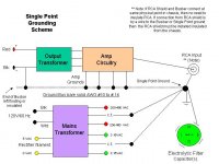
I'll make a diagram of both cases, Single Point Bus Bar Ground and also of the Single Point Star Ground and post later this week.
Bye,
On 5AR4, 5V4, GZ34, GZ37; Pin #8 is where the rectifiers cathode and filament meet so this is the pin that must go to the junction of the first capacitor and the choke input or first voltage dropping resistor.
With 5U4G and 5Y3, pin's 2 and 8 are pretty much interchangeable. Nevertheless it's a great idea to always wire octal rectifier circuits for the first case (5AR4) etc. so one can do some tube rolling between 5U4 and 5AR4 types.
I'll make a diagram of both cases, Single Point Bus Bar Ground and also of the Single Point Star Ground and post later this week.
Bye,
On the S.P. ground approach...
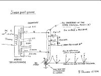
Here's my sketch (my marker was a bit rough!) I attached the file but can't seem to copy into the message (how do I copy and paste into the post?)
It gives the general idea of what I said.
I ground all PSU cap negatives, the center taps from the HV
secondary and the Signal Tube filament secondary and the RCA shield and one end of the Busbar to the same physical point on the chassis.
Should the RCA be located away from this, then the shield must be installed insulated from the chassis and a wire run to the single point ground.
This has worked for me every time.
The grounds from the actual amplifier circuitry can be also soldered directly to the same physical point as the S.P., but I typically run a #10 AWG Bare Solid wire (from leftover Romex) as long as I need and leave one end floating (insulated from chassis) and the other end connected to the S.P. Ground location.
Attachments
@rich
Very nice schem!
Some questions:
Can I connect all the DC grounds from the amplifier at one point (not chassis point) and then connect this point at SP?
If I have two channels, can I use two bas bars? Or two points, one at each channel, and then connect them at the SP?
Very nice schem!
Some questions:
Can I connect all the DC grounds from the amplifier at one point (not chassis point) and then connect this point at SP?
If I have two channels, can I use two bas bars? Or two points, one at each channel, and then connect them at the SP?
Yes in both cases.
You can collect the DC Grounds from the amp circuitry at one point on a tag board and then run a wire to the SP ground point.
This would be an 'equivalent' approach and help with the wiring layout and # of wires to be soldered together at the same node.
On a stereo amp you can run two Busses tied together at the SP point and then aggregate the grounds independently for each channel.
The most important ground connections for the lowest hum are made by soldering at one single point all of the Power Supply capacitor negatives, the HV Center Tap and the Filament center tap and finally the Bus Bar.
Bye,
Interesting questions about variations of a theme. I cannot say that I have experiented with scenarios that don't connect DC grounds to the chassis.
There are many schools of thought regarding methods of grounding amplifiers. I am sure that some manufacturers use other methods with much success, while others just follow the National Electrical Codes for safety.
I have to agree that there may be cases where mysterious ground loops are created between amplifier and preamplifier connections, it has happened to me several times.
One connection that I have omitted in my diagram that should be included is the (P.E.) or Protective Earth. In my country, our electrical system uses a 3rd wire that is connected to the chassis as well as having it's own independent wire that connecting back to the electrical panel earthing rod tie block.
The purpose of this ground is to prevent the creation of shock hazard on a metal chassis. The 117VAC mains consists of 3 wires. Black = HOT, White = Neutral and Green = P.E.
It is this 3rd P.E. wire that is connected directly to the metal chassis (not necessarily at the same SP gound location, but highly recommended to do so) wire that can cause ground loops to occur in relation to the mains and other stereo equipment that may have different grounding schemes incompatible with one another.
Some Guitar amplifiers implement a 'ground lift' circuit that consists of a Single Pole 120 VAC, 3A switch in parallel with a 0.01 uF /1000 Volt ceramic disk capacitor tied to the chassis.
If by any chance one gets a ground loop at a venue or at home, the switch can be opened and the 3rd wire is AC coupled or lifted from the chassis via the capacitor. This can also be found on some Stereo Tube Amps i.e. the Caztech SE 5881 amp from Canada offered this option.
Ground Lifts eliminate the AC shock protection, but can solve some ground loops issues.
As far as the practice of building equipment that passes government safety requirements, most vintage equipment would not pass the current safety requirements of today with their two wire AC cords. Of course, unless the device is designed double-insulated, most modern equipment has a 3 wire power cord.
I am not famliliar with the SUN branded amplifiers that are mentioned here so cannot comment.
On the preamp ground scenario, it depends on how the Preamp is grounded. Some real ground loop problems occur when connecting ground wires between the respective components ground lugs (especially the one's for the Phono ground).
To date I have not built any preamplifiers so I can't say that Single Point Grounding would be as effective in Preamp circuits. I eventually plan to build a Balanced Circuitry preamp with 6SN7 tubes.... (maybe a 2006 project).
The idea is to always design for safety with the proper fuses and possibly an MOV rated at 135 Volts AC across the mains wires in case a catastrophic over voltage should occur at the AC outlet.
Double-insulated designs are the safest where the chasis is never in any danger of contacting High Voltage DC or Mains AC Voltage through internal component failure of physical shorts. Safety is the #1 priority, then a solution that sounds good follows.
"If it sounds good, but is not safe it is not good"
This is a subject that can be simple or complex, depending on the intent of the DIY hobbyist.
To be honest I do get a ground loop problem from most tube amps when my Dynaco PAS-4 preamp is warming-up and connected to a live amp. The PAS-4 implements a Chip 555 timer that triggers a N.O. relay to connect the RCA outputs after a 40 second tube warmup period (1.1xRxC = 40 seconds.)
The PAS-4 tube-warmup delay circuit leaves the relay in the N.O. (un-energized) condition that lifts the RCA outputs. After 40 seconds the relay is activated and the center pin's (+) on the output RCA terminals is connected.
After the relay connects the outputs the ground loop noise is instantly eliminated.
Where one can really get into trouble with ground loops is the connection of XLR balanced components to Single Ended input conponents (RCA's) using adapters. These are notorious for ground loop problems and should be avoided. Mixing Balanced Circuitry with Un-Balanced is a recipe for problems.
My friend has an Atmasphere MP-1 preamp setup (gorgeous) and uses some Cardas XLR to RCA converters that connect the output of his MP-1 to his Cary SE-300B amps. There is ever the slightest hum on the woofers with these adapters. We did not hear this hum when using his Cary's SE300B with my Dynaco PAS-4 as both are RCA based single ended designs.
Bye again!
BR/
- Status
- This old topic is closed. If you want to reopen this topic, contact a moderator using the "Report Post" button.
- Home
- Amplifiers
- Tubes / Valves
- earthing!!!!!!!!!!