causes of hum
poor grounding of inputs--very loud!
ground loop--not loud
unfiltered power through filter system--can be loud but usually not, usually 120 cycles
pickup induced current on input lines--usually 120; not loud
high impedance series input -- too much resistance on grid of input/driver tubes; not loud
seems to me you should twist heater wires tightly if not done; position input wires away from heaters or anything with AC including pwer transformer
try moving your amp to another electrical outlet or power strip; keep it away from house currents in walls, on floors
I know all this sounds simple but I always get hum on new amps and manage to find causes and fix--you will too!
@SY
Hmmm
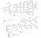
Yes the inputs grounding are crossing the filament leads as they going to star earth.
Do you believe my problem is over here? What do you say to place the filament leads L and R of the chassis? So, they’re away from the center where all the groundings come. Then they’ll be close to output leads but I think it’ll be better.
@fragman56
Thanks for this helpful information about causes of hum.I'll check one by one and hope I'll solve the problem.
Hmmm
Yes the inputs grounding are crossing the filament leads as they going to star earth.
Do you believe my problem is over here? What do you say to place the filament leads L and R of the chassis? So, they’re away from the center where all the groundings come. Then they’ll be close to output leads but I think it’ll be better.
@fragman56
Thanks for this helpful information about causes of hum.I'll check one by one and hope I'll solve the problem.
You might be having what is a confusing but simple problem or effect from ground current that simply escapes the builder.
I built a number of guitar amps. I built the first one and had the "Hummers".
The normal procdure for grounding was to have a short bus-bar from the ground spot on the chassis where the center-taps are grounded, to the filter ca[s on the fiberboard. The tube cathode resistors are grounded to the front copper plate. I ran the bus-bar all the way to the first tube. Hummmmmmm
The spot on any chassis where the PS is is "Hot"
You have to ground the RCa and input gain stage and inverter at the chassis where they are. The chassis is "Cold" there.
You have connected the "Hot" and "Cold" areas of the chassis together.
If you look at the underside of a vintage Heath for example, you will see a bus bar that runs along from the output tube Kathodes to the PS.
The grounds for the input tube stages and the RCA jack are grounded at the chassis away from the PS AC influence.
If the third wire is at the same spot as the center taps, then the third wire will take the AC influence on the chassis away to ground.
Another problem is that the power tranny puts a AC field through the chassis. Where the power tranny is, there will be a AC influence in the chassis.
Does the amp hum by itself?
There could be a AC difference between the chassis line stage and the power amp. Then Ac flows through the ground side of the input cables. See if you can measure a diff between the two with the cables unhooked. If you have the seperate pieces grounded with 3-wire cables, then you only need one side of the RCA cables grounded. Then AC can not flow from chassis to chassis. Or from the power amp to the phono cartridge or CD player.
I have been busy. I am short on time right now. HAng on and I can finger it out...
There was a store in Downey, CA called NET Electronics. It was in a Newberry Drug Store building. It was a old two-story building. The owners bought out all the Plush companys amps when they went under. They were all tube amps like Fender clones. I sat ubstairs and built amps, then put the completed amps out on my display area.
(around 1970)
The biggest amp they had was a six-6550 monster like the big orange and Hi-Watt units. 300 watts RMS.
You learn a lot working on *****y, high-gain Git-Amps.
I looked at the drawing.
Ground the PS stuff over in its area.
Ground the input stages over in their area.
DO NOT HOOK THEM TOGETHER!
The PS grounding should be by itself. The ground wire from the Ac should go to the PS ground.
Seperate the two top/bottom of the drawing. Ground the PS in it's area, and ground the input stages and the driver over in their area.
Then you won't hook the sensitive input stages to the chassis area where there is AC. The AC on the "Hot" area of the chassis actually raises the Kathode of the input gain stage and influences hum on the tube, the input pot, the RCA jack.
I have had to take the ground wires from the controls on a modified Git-Amp and "wander around" to find a place where I could put it and not get that hum in the background etc...
Geo...
You can hook a bus bar from the PS ground to the Kathodes of the output tubes but only that.
@Family Dog
Yeap it's 220R. My mistake
I think hummmm is gone!!

I measure a 20mVp-p 120Hz at the output with grounded input. It remains the same with open input but with a little noise on it.
Notice that I haven’t balance the outputs of the phase splitter, yet. And also no feedback at the moment.
I don’t think it will be audible after these two. With a small amount of FB it goes down to 10mV.
Have you any comments on these? Am I in a good progress?
@FranStar
I think you are the perfect guy to help me build my new guitar amp.
Which tubes do you believe is the best for a guitar amp?
When I’m ready I’ll post a new thread. Hope you will be there!
Yeap it's 220R. My mistake
I think hummmm is gone!!
I measure a 20mVp-p 120Hz at the output with grounded input. It remains the same with open input but with a little noise on it.
Notice that I haven’t balance the outputs of the phase splitter, yet. And also no feedback at the moment.
I don’t think it will be audible after these two. With a small amount of FB it goes down to 10mV.
Have you any comments on these? Am I in a good progress?
@FranStar
I think you are the perfect guy to help me build my new guitar amp.
Which tubes do you believe is the best for a guitar amp?
When I’m ready I’ll post a new thread. Hope you will be there!
I follow FranStar’s technique with HOT and COLD.
So, I use a multi-star ground technique.
I use one ground point at Left channel, one at Right and one at the PSU.
I grounded these points directly to chassis at each place. I use for the circuit grounds one screw of the phase splitter’s socket (for each channel) and another screw (power tranny’s) for the PSU. At this screw (PT’s) I had connected mains earth, too.
As I said I have only this 20mV 120Hz at the output with grounded inputs. I haven’t balance the outputs of the phase splitter, yet. I’m sure that this will reduce this hum dramatically. And with a little FB (about 8dB), hope to have SILENCE!
I will experiment with these today. So, I’ll post the news, soon.
Any further advice is acceptable.
I like very much the sound of this amp and I’d like to thanks all the guys at this forum that helped me.
Soon, I’ll post a new thread with the schem and voltage measurements on it. Maybe there are some hints and tips that I don't know, yet.")
I also don't like very much some measurements on the phase splitter.
So, I use a multi-star ground technique.
I use one ground point at Left channel, one at Right and one at the PSU.
I grounded these points directly to chassis at each place. I use for the circuit grounds one screw of the phase splitter’s socket (for each channel) and another screw (power tranny’s) for the PSU. At this screw (PT’s) I had connected mains earth, too.
As I said I have only this 20mV 120Hz at the output with grounded inputs. I haven’t balance the outputs of the phase splitter, yet. I’m sure that this will reduce this hum dramatically. And with a little FB (about 8dB), hope to have SILENCE!
I will experiment with these today. So, I’ll post the news, soon.
Any further advice is acceptable.
I like very much the sound of this amp and I’d like to thanks all the guys at this forum that helped me.
Soon, I’ll post a new thread with the schem and voltage measurements on it. Maybe there are some hints and tips that I don't know, yet.
I also don't like very much some measurements on the phase splitter.
This little hum that I have is still audible even if I apply a FB and bias the outputs of the phase splitter.

But I FOUND WHAT IS WRONG!!!!
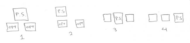
It’s the position of the trannies!

THIS MEANS A NEW ALUMINIUM!Again drilling and placing the components.The base is wooden so, I'll keep it.
Here's the story.
Remember that my PT is vertical and OPTs are horizontal.
I have them like (1)
Then I have done some experiments by listening only at the left channel and…
I remove the PT like (2) and, my god SILENCE!! Then I put the speaker at the other channel and hummmmmmm.
The only solution is (3) and (4).
DON’T TRY ANY OTHER.

But I FOUND WHAT IS WRONG!!!!
It’s the position of the trannies!
THIS MEANS A NEW ALUMINIUM!Again drilling and placing the components.The base is wooden so, I'll keep it.
Here's the story.
Remember that my PT is vertical and OPTs are horizontal.
I have them like (1)
Then I have done some experiments by listening only at the left channel and…
I remove the PT like (2) and, my god SILENCE!! Then I put the speaker at the other channel and hummmmmmm.
The only solution is (3) and (4).
DON’T TRY ANY OTHER.
Attachments
I have been away so I have not seen the fun. I worked on two Altec 304A amps. One hummed. One had a output transformer with one number off. This amp had a low hum in the background.
i found one with a complete matching # after two months of searching, and finally getting a Altec parts dude to go up to his attic and look on the third phone call!
The potted transformer looked esactly the same, but the inside core was at 90 degrees to the other. Amp was quiet. I should have posted this too, but I missed it.
Theses potted trannies still have a regular core inside. If the power tranny is at the wrong angle, it will put AC 60cps on the coils of the output.
The last amps I built, I put the trannies on opposite corners. Balances the chassis weight...
Glad you found it. hum usually is a dirty little secret that you have to hunt down...
So... When I build one for myself, I should make one ground point (directly on the chassis of course...) for Left channel, and another (separate) one for the right channel and a separate one for the PSU...
So it comes to 3 ground points on the chassis... Am I correct?
And is it ok to combine the 2 ground points from the 2 channels into ONE and make'em into "2 ground points in total on the chassis" ??
So it comes to 3 ground points on the chassis... Am I correct?
And is it ok to combine the 2 ground points from the 2 channels into ONE and make'em into "2 ground points in total on the chassis" ??
Hi James,
If you're building the left & right channels together with the power supply on only one chassis, then you should have only one earth point in total, not one for each of the amplifiers and power supply.
Otherwise, you run into the danger of the infamous "earth-loop" problem.
-Eric
If you're building the left & right channels together with the power supply on only one chassis, then you should have only one earth point in total, not one for each of the amplifiers and power supply.
Otherwise, you run into the danger of the infamous "earth-loop" problem.
-Eric
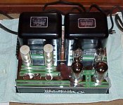
I just finished three MC-60s and they have really weird grounding runs. That chassis, (picture), has two big trannies that weigh lot.
The power tranny impinges AC in the chassis where it is due to the 60 cycle AC field around it. The filter caps impinge AC into the chassis where they are as the negative is on the chassis.
Then the chassis where the power supply is is HOT with AC
The third wire should ground the fpower supply AC to ground.
The preamp stages and inputs should be grounded at the right and left sides as in a Dyna 70. Then the first stages and inputs are grounded where the chassis is "Cold", away from the AC of the power supply...
Filter caps are tricky. The impinge AC to the chassis where they are.
The output tube cathodes can be grounded to the same spot where the center tap of the HV and the filter caps are..
According to science, the power amp is grounded third wire, then all the AC impinged on the front end stuff is "sunk" through the cables to the amp chassis and then third wire out...
The old gear had everything hooked to one big chassis, then a cap to nuetral if the plug was the right way...
In recording studios and you can do in Hi-Fi, all the cables have the ground hooked only to one end, and all the seperate gear goes to third wire. The the AC from each piece goes to ground seperate and none goes down the cables.
If a chassis is only .25V AC diff from another, then .25V AC is on your signal, ground lifted by that amount...
To: Resident
I have a Fender "Pro" chassis with most of the parts just sitting. Needs a output transformer..I have Dynas for EL34's but the 5881's from Sovetek are the cat's meaow for git..
The older Fender amps like the Deluxe, Pro, and the early twin are based on the 8K, 150 ohm cathode bias amp with two 6l6g's that give out 25 watts.
The tweed twins I built had 4K transformer or 8K /2 = 4K as four output tubes were used. Then the 8k primary is divided in half to 4K. This sounds really great and fat. The highs are sweet and not harsh. Kathode bias and 55 watts clean.
If you look at the different output stages you can use with 6l6 tubes, there is a 55 watt output stage with 3800Z primary.
Fender got cute and cut it to 1900Z primary for four tubes. You get 75-80 watts clean and it is harsh. this is the later Blond amps, Black Face, Silver face and on.
The Deluxes I built had the classic open-frame tranny at 8K for two 6v6 tubes. You could put two 6l6g or 5881's in as the bias was set in the middle.
The El34's are the true english sound in ultra linear.
5881's are the true Fender vintage sound at about 364V+
6v6s are the little screamers at 8K for two or 4K for four.
12ay7's for 1st stage has the early hot Fender sound with the deeper tone.
5751's are softer for blues and are the Stevie Ray Vaughn tubes.
If you use 5751's as the driver, then the whoel pre-stage will distort softly along with theoutput stage. That is the softer, bluesy sound.
The Cq12's have the mid crunch. The P's have broad band big tone. We used to use a Q and a P in each twin. Really got a big toney sound.
Not more that 175+ to the plates of the pre tubes. More than that and the pre tubes get harsher and have more hissssssss
Anyway, enough blather....
What sound? and what features???
Attachments
I noticed all the typos in previous. i just finished hasseling one of those Mac monsters...
If the power supply is in the center, and the AC comes in back center, then third wire ground and filter caps at center front..
The Dyna 70 is a good layout, just too small
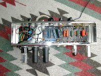
Here is a Deluxe head I built. It has two 6l6g tubes in it for about 20 watts. The metal tubes get ot all over and sound real Phat...
They have good sustain as the heat of the can makes the tube warm all over. it is a shame they done make them any more..
Real "purty" wiring...
If the power supply is in the center, and the AC comes in back center, then third wire ground and filter caps at center front..
The Dyna 70 is a good layout, just too small
Here is a Deluxe head I built. It has two 6l6g tubes in it for about 20 watts. The metal tubes get ot all over and sound real Phat...
They have good sustain as the heat of the can makes the tube warm all over. it is a shame they done make them any more..
Real "purty" wiring...
Attachments
Hi Franstar,
Thanks for detailed explanation of the different sounds that I can achieve.
All these are for guitar amps, though.
The amp I’m building right now is for hi-fi use. But I’m playing guitar, too.
I have built one guitar amp with a Fender preamp stage and Vox output stage, but with some changes on the circuit.
I’d like to build another one after this project and your information are very useful.
When I’ll start it I’ll post a new thread on diyaudio! Hope you’ll be there.
I didn’t believe that these metal 6L6 tubes are so nice. I’ll try to buy some of those just to give them a try. They’re not expensive, too.
Maybe they’re out of production ‘cause they’re not cool. You know, you don’t see inside the tube.
@FamilyDog
I have done it this way and no humm at all! SILENCE!
And it’s easy, too.
I’m rebuilding my amp so I’ll try to use only one earth point to chassis. Just to see the difference.
But my problem is that L channel is at the front of the chassis at the L side and R channel at the front of the chassis at the R side. The PSU is at the center and at the back place of the chassis. To use only one earth (chassis) point I must use long wires from the front, both L and R channels to back.
At the back place is main socket, too. NO long “earth” wire for this. Safety.
So, instead of using wires you can use the chassis as a wire for this purpose. I don’t think you have ground loops with this.
And a question-
I'm doing some plans for my new preamp.I'm planning to use a tube rectifier but the only good place to put it is very close to power transformer.Is there any problem except heating?
I mean hum problems or something similar.
The same thinking I have with output RCAs.
I would create a checklist like this and go through the amp one step at a time...
1) Make sure that your ground busbar is connected at only one place on the chassis (i.e. the RCA Shield). This is sacred, only one point, not two.
2) Make sure that your output transformer secondary has the black lead (the speaker negative) connected to the ground busbar. This is a common mistake to leave the OPT secondary floating (i.e. not soldering a wire from speaker negative to the busbar ground)
3) Make sure that you ground all power supply negatives and power transformer AC HV secondary center tap and all filament center taps to the same bus bar soldered as close together as possible.
4) Make sure that all your power supply capacitor grounds are connected to the same busbar. If you are using separate electrolytics, run a wire from each ground to the same point on the busbar that you have your HV center tap. If your PSU is a voltage doubler then it's one of the diodes that gets grounded to this point.
The function of a ground busbar is to connect to the chassis at only one point. Then all of your grounds (DC and AC) are connected to that busbar.
If you have a filament section 2 wire with no center tap (i.e. 0-6.3 Volts AC vs. 3.15-0-3.15 Volts AC) then you can solder a wire from one side of the filamet feed (either side is OK, but only one wire from one side) to the busbar ground.
The London Power book "Principles of Power" has a diagram that shows just how important a single point ground is to lowering noise in an amplifier.
The filament ground trick was used succesfully in the Leslie 147 amplifier.
If the hum still persists then you must check to see if by any chance you grounded one side of the power cord connecting to the primary. This is probably not the case but can make for a nasty shock. The primary connections must be floating and not connected to anything other than the mains fuse and the two primary wires from the power transformer.
You can try to reverse the power cord connection to the wall. This is a trick used many years ago when chassis were connected to one side of the mains in some Hallicrafter radios (dangerous.)
Hope this helps.
BR/
The function of a ground busbar is to connect to the chassis at only one point. Then all of your grounds (DC and AC) are connected to that busbar.
Do I need to form one bus bar for each channel, or make both channels to share single bus bar?? And should I place a separate bus bar for the PSU or connect all the PSU grounds to the same bus bar that both channels' grounds are also connected to??
It seem that your statement (which is the same as rest of others' ...) differs to FranStar's idea....
FranStar is telling us to make 2-3 ground connections to the chassis (1 for each channel and a separate one for the PSU), whereas you and rest of others are telling to make ONLY ONE connection to the chassis....
Which is truely correct then.....
Hi there:
There are two schools of thought with regards to grounding, especially in the Telecom industry where Single Point grounding is the buzzword that people like to hear, but not so easy to achieve.
I have found in the home brew amplifiers that I have built so far (four so far) that the implementation of a single grounding point on the chassis has worked for me every time.
To be honest I have not tried to ground my amps any other way but I cannot make a statement that says one cannot, many designers place multiple grounding connections at more than one point in the chassis and it works well most of the time.
So to answer your question; a single point grounding system is one where all grounds, direct or aggregated, are connected to the chassis at only one point; hence the term "single point ground."
Whether this means that you gather 20 individual wires and solder them together on one tag to the chassis, aggregate them on several insulated tab boards and then run a wire to the single point is of no major consequence. Depending on the amount of wires you make that choice along the way. The important single point connection is made by screwing down a Nut, Bolt and Locking Washer to the chassis or some other mechanically and electrically sound method for connectind to the chassis at a single physical point.
I used this method more than once already on my home brew amplifiers ... and it worked well, no noticeable hum.
What would I call this scheme.... 'single point star grounding' or a derivation of this. This is visualized as the aggregation of all grounds from insulated tag boards throughout the amp; soldering a ground wire from the aggregation points to a single point on the chassis, keeping the grounds simple, together and hum free. Of course wiring topology and transformer core orientation are key to lowering induced ground noise. Keep AC and DC wires as separate as possible.
I don't always follow the elegant wiring philosophy, which has proven to me that a good ground is better than artistic wiring techniques. You need a good ground first, then the tie wrapping can help dress the cabling later, assuming that one has cut the wires the correct length.
In this case of aggregation, the RCA's are insulated from the chassis and a wire is soldered from the shield to this point as well.
Another grounding scheme that I have used is to take a #10 AWG solid copper cable THHN or similar and strip off the insulation. The I connect one end of this bus cable to the chassis at exactly the same physical point where the RCA connects to the chassis. The RCA's shield in this case is 'not' insulated but screwed down to the chassis and a Round Hole Lug is soldered to the bus wire and then screwed down to the chassis with a good and sharp compression washer.
I scrape the chassis clean with a Dremel tool on all chassis connections and finish them off with a light coat of clear to make sure that no air tarnishes the connection for several years.
These single point grounds also aggregate the Mains HV center tap and any center taps from the filament sections.
Note: Rectifier filaments are never connected to anything but the tube socket itself and one pin of the socket is connected to the first PSU capacitor.
Sure hope that this makes sense to you. Let me know and I can probably send a diagram.
BR/
Sure hope
Note: Rectifier filaments are never connected to anything but the tube socket itself and one pin of the socket is connected to the first PSU capacitor.
Only for directly heated rectifiers, as the filaments = the cathodes, carrying HV.
So I guess I should stick on to the convensional method of having single chassis connection....
Sure hope that this makes sense to you. Let me know and I can probably send a diagram.
That'll be very helpful
My mail is: sendtojamesj@hotmail.com
Cheers,
JayJay
- Status
- This old topic is closed. If you want to reopen this topic, contact a moderator using the "Report Post" button.
- Home
- Amplifiers
- Tubes / Valves
- earthing!!!!!!!!!!