hello, I work in my project, one Single End EL34 in triode conection.
I find in Philips manual EL34 operate in triode concention need in Vb.......375 V
when design the power supply I must add to those 375V the volt drop in primari OPT and the difference to 0 the Vbias ?
+B = 375v + Vdrop OPT + Vbias(positive sing)
this is correct ??
I find in Philips manual EL34 operate in triode concention need in Vb.......375 V
when design the power supply I must add to those 375V the volt drop in primari OPT and the difference to 0 the Vbias ?
+B = 375v + Vdrop OPT + Vbias(positive sing)
this is correct ??
Plate supply voltage vs plate voltage
I assume your circuit is cathode resistor bias and the el 34 is an output tube connected to the output transformer?
Plate voltage is measured across the tube and does not include voltage drop across cathode resistor or anode load whatever.
Plate supply voltage is measured across the plate load to ground............I think.
Anybody else want to help him (me)? Just a guess here but Vb at 375 for el 34 is probably referring to plate voltage and does not include cathode resistor voltage drop. Add voltage drop across output transformer and cathode resistor to 375 (plate voltage) to get B+ or plate supply voltage.
In the Gospel according to Mullard, the SE triode-connected EL34 requires 250v plate-to-cathode, with -15v on the grid. Quiescent current is given as 70mA, so the cathode bias resistor should be 214 ohms. Assuming 5v drop across the OPT primary, your total B+ would need to be 250+15+5v = 270v.
Re: Plate supply voltage vs plate voltage
So based on what you've said, B+ would be 375V plus the drop across the OPT primary. Either way it's not going to make a massive difference to the distortion or output power. If you want it cathode biassed, you'll need to add the drop across the cathode resistor too.
Now this can be a bit tricky depending on which manual you look at. I always assume that B+ refers to the supply rail and Vb the voltage measured at the plate. Unless it specifically states otherwise, then you can assume that the cathode of the tube under test is grounded, and the bias voltage applied to the grid.alejo said:hello, I work in my project, one Single End EL34 in triode conection.
I find in Philips manual EL34 operate in triode concention need in Vb.......375 V
when design the power supply I must add to those 375V the volt drop in primari OPT and the difference to 0 the Vbias ?
+B = 375v + Vdrop OPT + Vbias(positive sing)
this is correct ??
So based on what you've said, B+ would be 375V plus the drop across the OPT primary. Either way it's not going to make a massive difference to the distortion or output power. If you want it cathode biassed, you'll need to add the drop across the cathode resistor too.
EL34SE
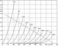
I don't have a Philips manual so I can't comment on the operating point suggested. However, I have attached a copy of the EL34 triode curves with a 5K loadline (i.e. for an OPT with primary impedance 5K). Assuming idle plate voltage of 375V, the grid would be need to be 32V more negative than the cathode to set bias and keep within max plate dissipation at idle. This means 32V has to be dropped acrossed the cathode resistor (bypassed by suitably sized capacitor). The idle current at this point is about 67mA, so R = V/I = 32/0.067 = 477.6 ohm. This is the cathode resistor value. The DC drop over the OPT primary also has to be considered, for something like the Hammond 125ESE this is about 90 ohm so V = IR = 0.067*90 = 6V. The B+ has to provide all this DC voltage (i.e. across the cathode resistor, the EL34 and DC drop arcross OPT primary) so B+ = 32+375+6 = 413V.
Also, since the grid sits at -32V, for full output power (in class A1), the driver stage has to swing 64V peak to peak.
I have assumed cathode bias. Also, I have not checked the operating point for sensibilities (apart from plate dissipation - which is about maximum) - it's really just an example
The EL34 triode curves were from Audiomatica's website
Attachments
Re: EL34SE
alejo: all the above is a good example of how to calculate it all out, but I wouldn't exceed a plate dissipation above about 80% if you want some life from the tube.audiousername said:I don't have a Philips manual so I can't comment on the operating point suggested. However, I have attached a copy of the EL34 triode curves with a 5K loadline (i.e. for an OPT with primary impedance 5K). Assuming idle plate voltage of 375V, the grid would be need to be 32V more negative than the cathode to set bias and keep within max plate dissipation at idle. This means 32V has to be dropped acrossed the cathode resistor (bypassed by suitably sized capacitor). The idle current at this point is about 67mA, so R = V/I = 32/0.067 = 477.6 ohm. This is the cathode resistor value. The DC drop over the OPT primary also has to be considered, for something like the Hammond 125ESE this is about 90 ohm so V = IR = 0.067*90 = 6V. The B+ has to provide all this DC voltage (i.e. across the cathode resistor, the EL34 and DC drop arcross OPT primary) so B+ = 32+375+6 = 413V.
Also, since the grid sits at -32V, for full output power (in class A1), the driver stage has to swing 64V peak to peak.
I have assumed cathode bias. Also, I have not checked the operating point for sensibilities (apart from plate dissipation - which is about maximum) - it's really just an example
The EL34 triode curves were from Audiomatica's website
Re: Re: EL34SE
True... that was just an example. I haven't even calculated the output power. All depends on how much the valves cost I suppose.
Brett said:alejo: all the above is a good example of how to calculate it all out, but I wouldn't exceed a plate dissipation above about 80% if you want some life from the tube.
True... that was just an example. I haven't even calculated the output power. All depends on how much the valves cost I suppose.
If you use 413V B+ with audiousername's numbers, you'll quickly cook the tube.alejo said:Thank you very much to all, I am going to experiment with 375V and 413V in the +B supply to see that differences I obtain.
Alejo.
I ran a couple of similar setups quickly in SEAmp CAD and came up with;
B+ = 375V
Ia = 67mA
Rk = 420 ohm
Vg = -28V
Pa = 21.4W or 76%
Pout = 3.7Wrms
B+ = 415V
Ia = 62mA
Rk = 530 ohm
Vg = -33V
Pa = 22.2W or 79%
Pout = 4.76Wrms
Both assume a 5k load and about 450 ohms of primary resistance.
Brett, I want buil this amp with One Electron Transformer UBT-3
Specifications:
Primary impedance: 3000 Ohms
Primary resistance: 286ohms nominal
what say your "SEAmp CAD" if I use:
B+ = 375 V
Rk = 370 Ohms
I want to obtain 6 Wrms in loudspeaker with EL34 as triode and 3000ohms.
thanks
alejo
Specifications:
Primary impedance: 3000 Ohms
Primary resistance: 286ohms nominal
what say your "SEAmp CAD" if I use:
B+ = 375 V
Rk = 370 Ohms
I want to obtain 6 Wrms in loudspeaker with EL34 as triode and 3000ohms.
thanks
alejo
Your op point was running the tube at 92% dissipation, a bit hot for my taste. Dropping Ia back to 67mA and Rk up to 440 ohms, I got 4.85Wrms (or less than 1dB difference, effectively inaudible) but at 8% THD, nearly all 2nd harmonic at 80% plate dissipation.alejo said:Brett, I want buil this amp with One Electron Transformer UBT-3
Specifications:
Primary impedance: 3000 Ohms
Primary resistance: 286ohms nominal
what say your "SEAmp CAD" if I use:
B+ = 375 V
Rk = 370 Ohms
I want to obtain 6 Wrms in loudspeaker with EL34 as triode and 3000ohms.
thanks
alejo
Don't have time to mess with other op points at the moment, but if you have the parts, try it and see what you think. I have no idea of what you're actually looking for, and where you're willing to make compromises in the sonic stew to get the performance you're looking for. If you have very efficient speakers, the combination above might be excellent, but if you run the amp harder, then it might just sound like mud. I dunno. 6W is probably feasible, but maybe not with a 3k OPT.
PS: I don't like SE's much except for guitar amps, so I might not be the best person to ask for where to set it up to get a specific sound. I'm just throwing around numbers in a calculator to get you started.
As I said before, the operating point I chose as an example runs at 375V between plate-cathode, and about 67mA idle current, so Pd = 375*0.067=25.1W, marginally over the 25W spec for the EL34. If you want reasonable life from your valves I suggest you use a different operating point.
For the record, I wasn't being critical of your earlier posts (they were very good), rather adding in extra info as I'm not sure alejo has a good understanding of how to determine operating points etc.audiousername said:As I said before, the operating point I chose as an example - (my italics)
alejo, if your understanding of tubes, operating points and how to specify them isn't great, read the atricle at Tubecad entitled "Grounded Cathode Amplifiers" as it will explain a lot.
Operating Points, Power Output, Distortion Calculations etc....
Steve Bench has written an excellent introduction to determine power output, likely distortion characteristics and an introduction to load lines at http://members.aol.com/sbench101/ (the Of Loadlines, Power Output and Distortion section - just keep scrolling down)
It might take a few reads to take the information in (it did for me anyway), but it is a well written introduction to basic theory.
Brett: No offence taken. I just don't want to be responsible for the early death of expensive NOS EL34s (if that is what alejo is using)
Re: Operating Points, Power Output, Distortion Calculations etc....
I'd forgotten about that one. Steve's pages are always a great read, especially that LCR phono stage he did recently, and the Matrix amp.audiousername said:Steve Bench has written an excellent introduction to determine power output, likely distortion characteristics and an introduction to load lines at http://members.aol.com/sbench101/ (the Of Loadlines, Power Output and Distortion section - just keep scrolling down)
It might take a few reads to take the information in (it did for me anyway), but it is a well written introduction to basic theory.
Great, just wanted to be sure. I'm also hoping that no NOS tubes die in the path of knowledge.Brett: No offence taken. I just don't want to be responsible for the early death of expensive NOS EL34s (if that is what alejo is using)
Buy a cheap new EL34 to test with, then swap in the NOS tubes once you're sure everything is OK with the circuit. That way any mistakes can be found without killing a good tube.alejo said:Hello. I am very happy with yours helps.
My EL 34 are Philips NOS date 1973 (I think.or 1974). They are expensive.
I`ll try operate this in +B 375V and arround I=50mA to
60mA
thanks boys.
Hi,
I have checked my old schematics with EL34 SE and russian 6H8C (latin -6N8S=6SN7). EL34 were TESLA or RFT.
Ua(EL34) = 265 V
Ro'=2,3k (Ro=4 ohm)
Current source (CS) instead of cathode resistor (LM337 + 22 ohm POT) bypassed by a 1 uF capacitor in automatic bias of EL34. CS sounds better IMHO to simple cathode resistor || cap. More lively. If you use LM337 you can mount it to amp conducting chassis (ground potential on TO220 metal element).
Tube full wave rectifier 5u3c (latin=5c3s - russian equivalent for 5U4-G) with RC filters. Sounded well, but I finally moved to Russian indirectly heated triode (IHT) 6c4c (l. 6s4s = 6B4G DHT). Good stage and details.
- Status
- This old topic is closed. If you want to reopen this topic, contact a moderator using the "Report Post" button.
- Home
- Amplifiers
- Tubes / Valves
- calculate +B in EL34 SE triode conect