Biasing Thoughts
To know if you are in the tubes max dissapation range, it is the current in MA times the voltage across the tube. If there is a Kathode resistor, then the voltage across that is ignored. The tube is dissapating the power from the plate to the kathode.
You can get faked out by amps running lower plate currents. If you have ever worked on a vintage Class-A amp, you will find sometimes high idle currents.
I rebuilt two old Altec amps. They were running 6550s at 42 watts each tube. You could cook eggs on them. The Peerless output trannys were small. (A340-A amps)
I thought the idles were wrong, but when I got schematics I found them dead on. I lowered the idles a small amount so the amps were slightly in the AB region and then they had better dynamics and the tubes were at a cool 37 watts each.
One of the reasons for high idle currents is to set the magnetic field in the output tranny to a certain place to get the characteristics desired.
They used to wind trannys in very unique ways so their characteristics change with current. Then the wole output stage is more linear as the tranny is working against the tubes non-linear curves.
6L6GC = 30 watts max diss (each tube)
36 ma X 350 volts= 12.6 watts
72 ma X 350 volts= 25.2 watts
In a typical Fender Git-amp running the usual high plate volts
45 ma X 450 volts = 20.25 watts
In these amps I usually set for 22 watts as the 6L6 likes it right there. The bass and mid tones are full, and the tube is still running cool. But to get the original specs on a Hi-Fi amp, the load on the primary of the output tranny has to be right so the magnetic field is high enough. A pretty wacked science.
Companies like Fisher and Leak had this stuff down pat.
If a amp was running lower plate voltage
100 ma X 250 volts = 25 watts
I have worked on several early amps running the above.
All running 6L6G or the metal 6L6 tubes. I like the metal ones in early amps as the whole tube gets hot and helps the current flow. A little deeper soundstage with these tubes.
Back then cooking the tubes was no big deal as they were cheap. The current itself does not heat the tubes. It is the total power so amps like these do not run that hot.
Max Kathode ma for a 6L6 tube is hard to find. Data books often repeat info. Also the 6L6 is not considered a high-current tube. The EL34 was invented to be the classic class AB tube with the ability to handle high Kathode currents.
For this tube max is 150ma. Running in Class-A or AB, fixed or Kathode bias results in the same power. The classic for two 6L6 tube with 250 ohm Kathode resitor is 25 watts for two tubes.
Your amp, probably is trying to imatate a vintage amp running at 8K primary, with a 250 ohm Kathode resistor.
You need to know what the supply can handle also. You amp could run easy 72ma per tube, if they were trying to load the output trannys to get better specs from them.
So your amp could have been designed to run 72ma per tube, but you need to know what the supply can handle. If you put a VOM on the cathode set resistors, and the amp is AB, the current should swing up when the stage is driven. Class-A it should change little.
They might have been trying to copy a old 1oK primary amp that ran a typical 12.5 watts, very clean, with high idle to load the trannys and get a lush, deep sound.
Then they chickened out and went 5K to get more power. You need to fuss around and see what sounds best. I found below 17 watts idle, the 6L6 falls off. It depends on how deep into class AB the amp is. It could go from 12 watts idle to full pop at 5K primary. A 8K or 10K primary means less variance in output stage current..
Hi
I have not seen the circuit so I do not know what Zaa is?
The best way to check is to play horns, piano, drums and other quick bursts of sound. If you hear harshness or modulation, then the transformers are failing or the tubes are not that matched to the trannys.
I did a upgrade to one of those Chinese amps and the results were about 20% more clean power and much better sonics.
I ended up running EL34s as they matched the 5K primary much better. The 6L6 is much sweeter at 7600 or 8K.
At 65ma at 430v , you are at 27.95 watts. I have always found this tube is happy at around 25 watts. This would be around 58 ma.
The real problem is plate voltage too high. This tube is much sweeter at 350+
I built a nuber of Fender Twin clones and I did not want to make a harsh sounding amp. I got the power tranny from AES so I ended up at 354V+. Then the output stage was quiet and sweet.
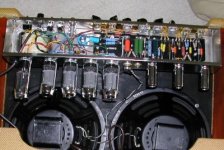
See pic. This is one of the Twins. Four 5881's in Class-A =50 watts. I could also run 6V6s and get a "Double Deluxe" amp.
4K primary and tons of bass..
------------------------------------------------------------------------------------
I use Metal-oxide 5W resistors as they are non-inductive. I use a 30 ohm from each Kathode to the main resistor.
So two 30 ohm M-Os and one 440 ohm = 470 ohm.
At this resistance it should be a 12. watt amp at 8K to 10K primary?
I would run around 55ma so you are close to 23 watts which I found is the sweet spot for these tubes. They will drive up to full pop from here.
If the amp is a little biased into AB, then the dynamics of the output stage are increased. I do this as standard routine.
------------------------------------------------------------------------------------
Some tubes like EL34s and 6550s are made to "Sit on their Butts" so the run high idle currents.
I also run 12K carbon-film 5% for grid resistors. A little neg feedback at the grid also relaxes the load to the driver and it has better dynamics then. Tubes get "too close" and the circuit chokes up.
I have not seen the circuit so I do not know what Zaa is?
The best way to check is to play horns, piano, drums and other quick bursts of sound. If you hear harshness or modulation, then the transformers are failing or the tubes are not that matched to the trannys.
I did a upgrade to one of those Chinese amps and the results were about 20% more clean power and much better sonics.
I ended up running EL34s as they matched the 5K primary much better. The 6L6 is much sweeter at 7600 or 8K.
At 65ma at 430v , you are at 27.95 watts. I have always found this tube is happy at around 25 watts. This would be around 58 ma.
The real problem is plate voltage too high. This tube is much sweeter at 350+
I built a nuber of Fender Twin clones and I did not want to make a harsh sounding amp. I got the power tranny from AES so I ended up at 354V+. Then the output stage was quiet and sweet.
See pic. This is one of the Twins. Four 5881's in Class-A =50 watts. I could also run 6V6s and get a "Double Deluxe" amp.
4K primary and tons of bass..
------------------------------------------------------------------------------------
I use Metal-oxide 5W resistors as they are non-inductive. I use a 30 ohm from each Kathode to the main resistor.
So two 30 ohm M-Os and one 440 ohm = 470 ohm.
At this resistance it should be a 12. watt amp at 8K to 10K primary?
I would run around 55ma so you are close to 23 watts which I found is the sweet spot for these tubes. They will drive up to full pop from here.
If the amp is a little biased into AB, then the dynamics of the output stage are increased. I do this as standard routine.
------------------------------------------------------------------------------------
Some tubes like EL34s and 6550s are made to "Sit on their Butts" so the run high idle currents.
I also run 12K carbon-film 5% for grid resistors. A little neg feedback at the grid also relaxes the load to the driver and it has better dynamics then. Tubes get "too close" and the circuit chokes up.
Attachments
FranStar: From context, Zaa is the anode to anode load impedance.
kooltubes: The calculator is probably accurate, but all it does is figure out what idle current gives a fixed percentage of the rated plate dissipation, a pretty simple calculation. And that doesn't tell you anything about what the optimum idle current is for a given situation. Unfortunately, there is no good substitute for spending an hour with a printer, a ruler, a pencil, and some scissors to lay out load lines on the tube Vp/Ip characteristic curves.
kooltubes: The calculator is probably accurate, but all it does is figure out what idle current gives a fixed percentage of the rated plate dissipation, a pretty simple calculation. And that doesn't tell you anything about what the optimum idle current is for a given situation. Unfortunately, there is no good substitute for spending an hour with a printer, a ruler, a pencil, and some scissors to lay out load lines on the tube Vp/Ip characteristic curves.
Then this is a "cranked" 12.5 watt amp. You can run6l6 tubes from 12.5 K down to 3800 ohms for 45 watts. Fender, in their greed for power came up with 1900 ohms and four tubes. 3800/2=1900
It sounds like crap though. The higher load takes the harshness out. I went fr 8K/2=4000Z as Kathode bias 25W is 8k/two tubes.
THen they push what is a clean 12 watt amp to 20 by driven it hard and I would say biasing into AB. Then I would think the idle should be down around 17 watts so it can jump up to full pop.
The original 12.5 watt amp would be idling at 25watts per tube
or around 55-58 ma. I would go 50 for power, higher for deep tone. Need to know the limits on the output tranny.
The stcikly problem is that you do not know how the tranny does through current changes. Fisher and Citation for example wound trannys so they changed characteristics as they went through the current range.
I came upon this when in a debate about replacing a Citaton tranny and the channel did not match sonicly with the other..
Best to to sound tests. Less paper work also...
Guys back then could throw slide rules around like magic...
Franstar have in mind that none of the Hi-Fi speakers out there are exactly 8 ohm. They're around 5 to 6 ohms.
So, you believe that at 350V and Ia around 72mA are the better results for 6L6GC?
I can step down the anode voltage by increasing the resistors on my RC networks.Better filtering,too.I don't use choke.I prefer Shindo style filtering.
So, you believe that at 350V and Ia around 72mA are the better results for 6L6GC?
I can step down the anode voltage by increasing the resistors on my RC networks.Better filtering,too.I don't use choke.I prefer Shindo style filtering.
For this amp, that is much closer to the original circuit values. New builders get “high voltage happy” and think they can sell more if they squeeze a few more watts out with another 100 VB+ on the tubes. The 6L6 gets harsh after 350+ and more unstable. You can’t go by guitar amp output stages as they are not correctly designed. They are just too much of everything.
This is why I do not get power trannys from Git-Amp suppliers so I can run lower B+ and have a much sweeter, quieter amp.
The original tubes for this circuit were 6L6G or the Metal version. There were eight different 6L6 tubes around 1945. Also 5881s. I think the 5881s or Kt66 tubes are the ones really intended to be the top dogs> 6L6 tubes were considered low-fi back then.
Then 5881s or Kt66 tubes at about 350B+ and around 60 ma = 21 watts. This would be right on the nose for 6L6G and KT66 and would be true Class-A biasing.
If you uses 6L6GC or the new 5881s you could go up to 72ma.
I do not know the limits on the tranny though.
You will find some older amps used big wirewound resistors in the B+ supply and just let them heat the chassis up. More “R” gives better filtering. More stages also. I use a smaller cap at first, then build to a big cap right close to the output tranny so the current source is close.
I know that speaks jump all over with impedance. That is why high idle currents and low Z primarys with four tubes became popular. More dampening to the load.
What is the output tranny? (make etc.)
------------------------------------------------------------------------------------
I need to make one more post on this subject. I rarely have time to talk. Sometimes my brains are soup because I am doing ten diff projects at once. I forgot to discuss the main aspect of biasing tubes for A or AB.
The biasing difference in a tetrode or pentode that makes it run in AB mode, push-pull or single ended, is when the screen voltage is less than the plate voltage.
If you take a 6L6 tube, running at 450V+ plate, and 450V+ screen, Class-A mode, and drop the screen voltage to 300V+, then you will have to drop the grid bias to about –15V to bring the idle current up to about 30% of the Class-A level.
Then with the tube “held” by a low negative bias, the driver stage can drive the grids to positive and the tubes to full pop. The tube swings from a low idle to the max for the output transformer or tube dissipation.
The lower negative grid bias means the driver stage has a lot less –bias to overcome. Then the driver tubes can run at lower levels and the general dynamics of the entire amp is greater. The high negative feedback dampens this down.
Then running a triode in Class-A, (the only way you can) with low or no negative feedback will give good transit response.
If you look at older circuits like Citation or Fisher, you will see separate power supply chains and sometimes regulators for the screens. I worked on one amp that used a 6V6 to regulate the B+ for the screens and then the preamp power was taken off that.
Fisher 90A = 625B+ on plates, 232B+ on screens, -15 grid bias.
This is typical of the big high-power AB amps.
The king of AB is the EL34/6CA7 tube.
It can run 800B+ on Plates, 425B+ on screens, 150MA max Kathode current
The Fisher 90A got 120 watts out of four, super Williamson circuit.
Hight current tubes like the EL34 put out the same power in Class-A as fixed bias. Two EL34s in Class-A, 232 ohm Kathode, gives 45 watts into 6500Z. Only 5 watts more at 5K in Dyna amps with fixed bias.
The 6550 is the other one. It can run up to 175 ma Kathode current. Running 600B+ on plates, 300B+ on screens, -31 grid bias, you get 100 watts into 5K primary. Sun amps and a few others used this circuit for ages. Also in Ultra-Linear mode.
So the way to determine if a amp is Class-A or Ab is to see if there is a difference between the plate and screen voltage. If it is less 50 volts or less then the tube is “biased” for Class-A. If greater, then the tube is going into the AB region.
Triodes run in “Class-A” by having the idle as high as any positive swing when driven.
A 12ax7 idling at .05 ma, will go up when driven. If it is idling at 2 ma, then it is already as high as any positive swing will take it.
This should help.
George...
The ToneMaster
Hi Franstar,
Thanks for the detailed explanation. OPTs and power transformer is from GKlab.
There’s no any problem with the limits of them. Power tranny is rated at 340Vac/500mA and OPTs can handle currents up to 150mA at each half of primary.
I’m building an Ultra-Linear P-P amp with one pair of 6L6GC at each channel. Screens are connected to UL taps with 470R resistors.
I’ll bias them at 350V and Ia at 60mA-70mA, as you suggested me. Hope I’ll like it.
I’ll step down the anode voltage with resistors. I like this idea ‘cause I’ll have better filtering, too. You saw this filtering in old amps? Do you believe it’s a good idea to use it on other amps, too?
I order the tranny to have anode voltage about 430V! And now, by mistake, things become better in my design ‘cause I’ll have 350V with much better filtering.
My problem is that I have some hum problems. If you‘d like to help me upon this please go over
here
When they built early vintage amps, having something hot and big under the chassis was no big deal. I always save high-wattage wirewound resistors. I always have the really big cap at the end of the chain. Then the resistor gives a brake on the start-up current to charge the cap.
If you have about 200mf right at the output tranny, then the output tubes will draw from that. you need just enough to make the rectifier work as the first cap...
Using a resistor chain is fine. It takes room so a lot of builders skip it for skimpier filtering.
You can get hum if the filiments are not grounded. The usual is to ground the center tap on the filiment winding. You can have a 100 ohm resistor from ground to each tap.
If you go DC, like I do, then a .25mf/50V cap from the + to ground does it.
How are you doing the filiments?
My filament windings are center tapped and I had grounded them.I don't know why I have this little hum.
Please read my thread if you like to help me.Follow this link
http://www.diyaudio.com/forums/showthread.php?s=&threadid=43923&perpage=10&pagenumber=1
Please read my thread if you like to help me.Follow this link
http://www.diyaudio.com/forums/showthread.php?s=&threadid=43923&perpage=10&pagenumber=1
Classic 6L6 Amp
If you look at 6L6 amp circuits, especially guitar amps, the classic is about a 10K resistor between the plates and the screens. This gives a little lower screen voltage so the idle will not be too high with 250 Ohms Kathode resistance.
If you want real smooth Class-A
Then Ultra linear with Hammond's 7600ohm 25W tranny, and run 250 ohm/10W Kathode main resistor, split with two 30 ohm/3W resistors to each kathode. Bypass the 250 ohm resistor, leave the 30 ohms dry as Neg feedback fot each tube and to control idle current.
Bypass with a metal-poly or oil cap if enough room.
Anything over 20MFD is actually enough. I have tested and found the large values to be unneeded.
I use two 5W metal oxide for the 250 ohm, and 3W metal oxide for the 30 ohms, a "Y" circuit. This works fantastic for better response and clarity.
I use 15K carbon-film resistors in series with the grids, 330k from output of the coupling cap, in front of the grid resistor to ground.
I can scan a circuit. I have built several Ultras with Sovetek KT88's and they sounded really sweet. Used 6sn7's biased up from stock...
Franstar,
thank you for your detailed answer.
So you think it's better to use UL with 7600 primary.Notice, that I will order the OPTs from a local winder and the winder can wind them at any primary I wish.")
So if you believe that there's a better value close to 7K6 there's no any problem.
Are you sure for that?I have two 22uF Audyn MKP!!!
Are they enough to bypass the 250ohm?
Most diy-ers use from 100uF to 470uF.
Maybe for guitar amps 20uF is enough but for hi-fi use the amp works at more lower frequencies.Can you make it more clearer?
I suppose that I'll use overall NFB,too.Right?
thank you for your detailed answer.
So you think it's better to use UL with 7600 primary.Notice, that I will order the OPTs from a local winder and the winder can wind them at any primary I wish.
So if you believe that there's a better value close to 7K6 there's no any problem.
Anything over 20MFD is actually enough. I have tested and found the large values to be unneeded.
Are you sure for that?I have two 22uF Audyn MKP!!!Are they enough to bypass the 250ohm?
Most diy-ers use from 100uF to 470uF.
Maybe for guitar amps 20uF is enough but for hi-fi use the amp works at more lower frequencies.Can you make it more clearer?
Interesting bias method.I'll try it.Until now I thought that separate cathode resistors at each cathode was the best bias method.Bypass the 250 ohm resistor, leave the 30 ohms dry as Neg feedback fot each tube and to control idle current.
I suppose that I'll use overall NFB,too.Right?
No problem if you'd like to scan a circuit.It's always acceptable!I can scan a circuit. I have built several Ultras with Sovetek KT88's and they sounded really sweet. Used 6sn7's biased up from stock...
Good news!Per tests, the original 6L6 has the lowest distortion prospects of all the 6L6 family of tubes. I am in process of building such an amp with 4x 6L6 (PPP).
Which 6L6 do you prefer?What do you say about EHX 6L6?
by-passing output tubes
 I am doing fourteen things at once so I can't get back to the chats right away.
About foru years ago I cleaned out my work room and started up again. I had a lod two 6V6 Class-A 7600 ohm primary amp. I decided to "take it around the block" and check out all the concepts.
I found 20, but right around 50 gives a correct Square wave at 20 Hz. Sine wave response at power flat as a board.
The small amount of "dry" resistance increased the low end response to the lowest the gen would go.
I got a major increase using non-inductive metal-oxide resistors.
When you use a wire-wound resistor and a cap, you are putting a tuned circuit in the sensitive Kathode of the tube current path.
By using a small amount of dry resistance in a Y circuit, you are inserting a small amount of linear Neg feedback so the circuit is more stable, then over-all loop feedback needs are less.
Also using 15K in series with the grids is linear Neg feedback. I also use 33K in series with the driver grids. Thsi "seperates" the tubes. I did things to bring the tubes closer by lowering plate series resistors values etc. and the tubes got very unhappy and preformance dropped.
The grid current is small so even a 33K resistor is a small amount of Neg feedback. The loop feedback is used to make a unstable circuit stable. I have taken the loop off on old amps and watched the driver go out of balance and the amp go nutz as the loop was used to pull a unstable circuit together.
The idea is to make the overall circuit stable and balanced without loop feedback, then just "trim" with loop. Then the transit responses is up.
I am doing two Craftsman C-500 amps. The owner sent me KT-66's for them. I told him, and I am telling you guys, screw all tose "audiophile tubes, get the old metal 6L6G tubes and Sovetek 5881s. Great tubes. I really like RCa metal 6L6 tubes...
Let get some circuits scanned and send them..
use the 22mfd, 250 ohm, 30ohm and test. then with a living thing, you can really see what haps.
Tubes are very sensitive and there is more happining than some computer calculations...
What do you want to use for drivers? the 6SN7's are the classic and I have updated circuits for those.
I will scan the circuit for the prettiest sounding 5881 Ultra amps I ever heard. And that is out of a lot of amps..
Another deal. I was using 2.2k in front of the driver caps and 5.6k behind. Then the resistors push back against the cap and increase transit response, and the circuit sounds sweeter. You can use carbons for sweet, carbon film for tight and smooth etc...
I am doing fourteen things at once so I can't get back to the chats right away. About foru years ago I cleaned out my work room and started up again. I had a lod two 6V6 Class-A 7600 ohm primary amp. I decided to "take it around the block" and check out all the concepts.
I found 20, but right around 50 gives a correct Square wave at 20 Hz. Sine wave response at power flat as a board.
The small amount of "dry" resistance increased the low end response to the lowest the gen would go.
I got a major increase using non-inductive metal-oxide resistors.
When you use a wire-wound resistor and a cap, you are putting a tuned circuit in the sensitive Kathode of the tube current path.
By using a small amount of dry resistance in a Y circuit, you are inserting a small amount of linear Neg feedback so the circuit is more stable, then over-all loop feedback needs are less.
Also using 15K in series with the grids is linear Neg feedback. I also use 33K in series with the driver grids. Thsi "seperates" the tubes. I did things to bring the tubes closer by lowering plate series resistors values etc. and the tubes got very unhappy and preformance dropped.
The grid current is small so even a 33K resistor is a small amount of Neg feedback. The loop feedback is used to make a unstable circuit stable. I have taken the loop off on old amps and watched the driver go out of balance and the amp go nutz as the loop was used to pull a unstable circuit together.
The idea is to make the overall circuit stable and balanced without loop feedback, then just "trim" with loop. Then the transit responses is up.
I am doing two Craftsman C-500 amps. The owner sent me KT-66's for them. I told him, and I am telling you guys, screw all tose "audiophile tubes, get the old metal 6L6G tubes and Sovetek 5881s. Great tubes. I really like RCa metal 6L6 tubes...
Let get some circuits scanned and send them..
use the 22mfd, 250 ohm, 30ohm and test. then with a living thing, you can really see what haps.
Tubes are very sensitive and there is more happining than some computer calculations...
What do you want to use for drivers? the 6SN7's are the classic and I have updated circuits for those.
I will scan the circuit for the prettiest sounding 5881 Ultra amps I ever heard. And that is out of a lot of amps..
Another deal. I was using 2.2k in front of the driver caps and 5.6k behind. Then the resistors push back against the cap and increase transit response, and the circuit sounds sweeter. You can use carbons for sweet, carbon film for tight and smooth etc...
You mean 6V6 or 6L6?I'll build my amp with 6L6.About foru years ago I cleaned out my work room and started up again. I had a lod two 6V6 Class-A 7600 ohm primary amp. I decided to "take it around the block" and check out all the concepts.
7600 ohm of primary is good for 6L6 too?Or use sth close like 8K or ...?
I'll do it.use the 22mfd, 250 ohm, 30ohm and test. then with a living thing, you can really see what haps.
I can't wait for this. I'd like to order asap the OPTs to check it!
I already have them for drivers!What do you want to use for drivers? the 6SN7's are the classic and I have updated circuits for those.
I will scan the circuit for the prettiest sounding 5881 Ultra amps I ever heard. And that is out of a lot of amps..
No problem if you'd like to post a schem!
Do you mean the signal caps?After the phase splitter and before the grid?Another deal. I was using 2.2k in front of the driver caps and 5.6k behind. Then the resistors push back against the cap and increase transit response, and the circuit sounds sweeter. You can use carbons for sweet, carbon film for tight and smooth etc...
So,anode of phase splitter-2K2-cap-5K6-grid of 6L6?
I've just ordered the MOX resistors and now I'm planning to order the OPTs.
I'm planning to order them at 7600ohm with UL taps.
The winder suggested me to use only one tap at the secondary.8 ohm or 6 ohm.For better results he suggested me to order them with 6ohm secondary tap.What do you say?
I prefer with 4ohm and 8 ohm taps but the winder told me that it's much more better when all the secondaries are in parallel and not mixed ie in series and parallel.And at 6ohms because 90% of the speakers on the market have impedance around 6ohm.
Plitron have a nice article on this.But Plitron wind their TXs at 5ohm.
- Status
- This old topic is closed. If you want to reopen this topic, contact a moderator using the "Report Post" button.
- Home
- Amplifiers
- Tubes / Valves
- Help needed for a 6L6 Push pull amp