By making the output stage double as the phase splitter, you lose some of the advantages of push-pull, most notably cancellation of second (and other even order) harmonic distortion. At the cost of efficiency, complication, and reliability, the CS will help mitigate this.
The logic behind this is questionable.
The logic behind this is questionable.
A nice two stages P-P amp!
Go with an UL tranny, so you can hear it triode ,pentode and UL!Also try it with G2 ( screen ) something lower than 300V, say 200-250V.Just for an experiment.Some people like it better than pentode or UL.
Also try it without 470u.I thing this cap doesn't belong there.Read at diyparadise the original article about this amp.There's a reference about this cap that I don't remember.
it should take twice the signal drive as normal PP
Is this correct?

Thanks!
Simon
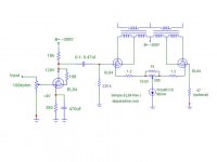
Electronic World published this circuit in 1961 with a 6C4 as input driver tube. This was before the time of low voltage ccs's, so there is just a resistor in the cathodes.
You can actually see this as a single ended amplifier (V2) with a opt current equalizing tube (V3) and active load. Ofcourse the amplitude on V3 anode will be lower than on V2, but the circuit vill cancel a lot of distorsion anyway. The second harmonic of the 6C4 is also in opposite phase to that in V2.
I think this circuit could also be tried with 6CW5/EL86's as output tubes, in triode or pentode operation, with even better performance than the 6BQ5/EL84. For a budget project, the low priced NOS 15CW5/PL84 are plentiful. same specs as 6CW5/EL86 despite the number PL84!! The only difference is that it takes 15V at 300mA for the heater.
http://triodeel.com/compact.html
JohanB
You can actually see this as a single ended amplifier (V2) with a opt current equalizing tube (V3) and active load. Ofcourse the amplitude on V3 anode will be lower than on V2, but the circuit vill cancel a lot of distorsion anyway. The second harmonic of the 6C4 is also in opposite phase to that in V2.
I think this circuit could also be tried with 6CW5/EL86's as output tubes, in triode or pentode operation, with even better performance than the 6BQ5/EL84. For a budget project, the low priced NOS 15CW5/PL84 are plentiful. same specs as 6CW5/EL86 despite the number PL84!! The only difference is that it takes 15V at 300mA for the heater.
http://triodeel.com/compact.html
JohanBI sew that this first circuit in diyparadise with CCs was revised by someone later on, back to a common resistor in the cathodes (as in the original Leibowitz circuit). See link below.
http://diyparadise.com/web/index.php?option=com_content&task=view&id=58&Itemid=26
I'm still puzzled about using power tubes (6BQ5 or later 1/2 5687) for driving the grid of the output tube. I think it's an overkill (and expensive) to use as driver, especially in pentode and UL-mode.
If not using a 6C4 (EC90) in the pentode mode operation, 1/2 12AT7/ECC81 (EC92/6AB4) will have enough gain and power also for the millercaps in triode mode. Will also give a nice 2:nd harmonic to partly cancel the resulting 2:nd harmonic in the first output tube.
JohanB
http://diyparadise.com/web/index.php?option=com_content&task=view&id=58&Itemid=26
I'm still puzzled about using power tubes (6BQ5 or later 1/2 5687) for driving the grid of the output tube. I think it's an overkill (and expensive) to use as driver, especially in pentode and UL-mode.
If not using a 6C4 (EC90) in the pentode mode operation, 1/2 12AT7/ECC81 (EC92/6AB4) will have enough gain and power also for the millercaps in triode mode. Will also give a nice 2:nd harmonic to partly cancel the resulting 2:nd harmonic in the first output tube.
JohanBI have two thoughts on this setup:
Yes, singly driving a diff-amp with a long tail causes the cathode of the driven tube to follow the grid halfway, so we're dividing the gain of the driver tube between the two outputs tubes. An EL84 in the 'first hole', as shown is not gonna get you there without a truly monster signal coming in the front - much greater than line level. A bigger gain low rp tube like the 6GK5 or similar would ameliorate this problem.
The CCS in the output tail does solve the horrendous output signal imbalance problem of the original Compact, but I don't know how thick on the ground CCS circuits are that can stay firmly in regulation at 80mA with only the 18v (or so) cathode lift of the EL84 outputs across them. Maybe somebody else here, like Stuart, can comment on this. If it don't fly, we could always build a little 50v or so negative supply for the tail.
Otherwise, why not try it? All the parts could be recycled if it doesn't sound good.
Aloha,
Poinz
AudioTropic
Poinz, is there a reason why you're running the 6gk5 at such 'low' current in your musical machine? My search for a high gain potent driver also led me to settle for 6gk5 (I'm running 12b4 as outputs so need 60Vpk-pk, times two , swing), intending to run it at about 10mA, 165V on the plate, into a CCS load.
Thanks for your circuit analysis, gents.
Cheers,
Simon
, swing), intending to run it at about 10mA, 165V on the plate, into a CCS load. Thanks for your circuit analysis, gents.
Cheers,
Simon
One day i'm going to build one of these using EL86's (I even bought the Tubes for it). I have no doubt that Yoe is correct is saying it sounds good. A bit more second harmonic than the usual PP design. I imagine it will have a sound somwhere between PP and SE.
My experience is the LM317 should work fine as the CCS, and as was pointed out - if you want to be safe build a simple little negative rail.
Shoog
My experience is the LM317 should work fine as the CCS, and as was pointed out - if you want to be safe build a simple little negative rail.
Shoog
What output power do you expect from the 12B4's and what B+ do you use. They have only 5,5W anode dissipation.
I'll still go for triode mode 6CW5 that can dissipate 13W (in triode) and u=8, Rp =800 Ohms, S=10mA/V. Will give at least 5 W output with much less p-p driving voltage. These sturdy TV sweep-tubes will also have a long service life.....
I'll still go for triode mode 6CW5 that can dissipate 13W (in triode) and u=8, Rp =800 Ohms, S=10mA/V. Will give at least 5 W output with much less p-p driving voltage. These sturdy TV sweep-tubes will also have a long service life.....
I second what Waveborn just said: Though I was thinking of UL +
Pentode till I scrolled down and seen that he had beat me to it....
Triode on the left works fine too.
Reasoning: Bottle on the left controls plate voltage swing for both
ends of the transformer. Bottle on the right is just complimenting
the resulting current and holding the shared cathode voltage close
to a constant.... In my thinking, a folded cascode.
Making the right side plate try to act voltage linear is redundant,
confuses left plate voltage, and right cathode current feedbacks.
And serves only increased voltage errors for both tubes. I'm not
saying such errors would sound bad or even needs to be fixed...
The most linear choice for the right side device is probably Sand.
I know that runs contrary to common sense.
kenpeter said:I second what Waveborn just said: Though I was thinking of UL +
Pentode till I scrolled down and seen that he had beat me to it....
Nobody can beat you to your own conclusions.
I'm confused on a couple of things here. Perhaps you can help me try to get this straight. FYI, most of my knowledge of this design comes from the sources already listed , and sites like this.
1. What IS the advantage of running an unbypassed common cathode resistor with the output tubes in a "follower" P-P format ?
2. Does a "follower" P-P format , with all else being properly set up , produce as much power output as a "true" P-P setup ? How does distortion compare between the 2 alignments ?
In laymans terms , I thought the advantage was that the unbypassed common cathode resistor acted as a form of local negative feedback by averaging the difference in cathode current draw between the output tubes.
The "follower" format , as far as I thought I knew , reduced even order harmonics (as does P-P) , but only required half as much drive as compared to "true" P-P .
I've wondered about this for a while, as the design by Mr. Lebowitz is said to be about 5-6 watts , which considering the fact he is using the outputs in Pentode, seems pretty low. Could that be the downside to using the "follower" format , less output than a "true" P-P setup ?
Anyone else notice the original schematic by Mr. Lebowitz has the Grid2 running higher voltage than the Plates ? Seems kinda strange to me. . .
I was thinking about something like this :
http://img521.imageshack.us/img521/3083/my6sl7gt6v6amp.png
I would really appreciate your knowledge about the "follower" P-P format, as I have been interested in using it based on what I think I know about it.
..................................Blake
Regarding my last post. . .
Should I just run this instead ?
http://img211.imageshack.us/img211/7360/my6sl7gt6v6ppamp.png
......................................Blake
Should I just run this instead ?
http://img211.imageshack.us/img211/7360/my6sl7gt6v6ppamp.png
......................................Blake
What output power do you expect from the 12B4's and what B+ do you use. They have only 5,5W anode dissipation.
~230V; power will be low but I'm restricted to a power X-former that is sized for 100mA which is one of the reasons why I picked 12b4. This is not a design from scratch but uses chassis + parts from an abandoned project. Besides that, 6cw5 surely looks like an interesting tube.
Simon
- Status
- This old topic is closed. If you want to reopen this topic, contact a moderator using the "Report Post" button.
- Home
- Amplifiers
- Tubes / Valves
- Any comments on this design?