In my PP amp (pleased see attachment), I'm using the 6SN7 as a differential driver for triode-mode EL34s. Each half of the 6SN7 has about 230v plate-to-cathode and is drawing about 4 mA. Cathode-to-ground voltage is about 40v. I've tried to avoid the low current, low plate voltage often seen in some early designs but I guess my 4mA per side is still pretty low.
I wonder if, in other people's experience, I would improve the sonics by reducing the common cathode resistor (currently 4.7k) and reducing the plate load resistors (currently 33k) to get a higher current?
I wonder if, in other people's experience, I would improve the sonics by reducing the common cathode resistor (currently 4.7k) and reducing the plate load resistors (currently 33k) to get a higher current?
Attachments
Using a current source to bias your differential driver circuit is an excellent idea, ring of two transistorized current sources work quite well for this.. Note that the current source should be floated off of a low voltage negative supply (-12V will work fine) which does not even need to be regulated, but should be reasonably well filtered. I have found that the bias voltage present on the cathodes of the 6SN7 is not enough for the current source to function properly with audio present on the cathodes - drives the current source to cut off on negative going peaks. Sounds very nasty, ask me how I know.  Using a current source for bias will improve common mode rejection, but more importantly improve AC balance. I think something on the order of 6 - 7mA per section is a good compromise. Plate resistors should not be much less than 20K.
 ")
Using a current source for bias will improve common mode rejection, but more importantly improve AC balance. I think something on the order of 6 - 7mA per section is a good compromise. Plate resistors should not be much less than 20K. Thanks very much for your responses. I don't have the bits & pieces to make a CCS for the driver at the moment but I'm going to try reducing the 6SN7 plate resistors from 33k to 22k, reducing the tail resistor from 4.7k to 2.7k and removing the 440 resistors in each cathode. This should increase the current in each half of the 6SN7 to about 7mA, whihc might sound better.
I also want to insert 1M resistors between 6SN7 plate and 6SL7 plate, to improve DC balance and introduce a bit of negative feedback across the driver.
BTW, what sonic improvement might I notice if I do use a CCS in the tail of the driver? I can understand ther need for it in the tail of the splitter, to achieve balance.
ray_moth said:BTW, what sonic improvement might I notice if I do use a CCS in the tail of the driver?
An unbelieveable improvement in transient response for starters...
Dropping the tail resistor will increase imbalance in the diff pair. Even a simple one transistor current source (you don't have to get fancy) will outperform that resistor.
Use your 33K resistors, use a simple current source (15-20 ma for the pair), and get the B+ up and you'll have a terrific driver stage.
Use your 33K resistors, use a simple current source (15-20 ma for the pair), and get the B+ up and you'll have a terrific driver stage.
Right, you've convinced me! How about if I use a PN2222A as a current source? I can get a useful neg. voltage from the 50v 100mA winding on my tranny and use it at the same time for neg. bias on the EL34s. Please see attachments to this and the next post (fingers crossed - this often fails!)
Attachments
I haven't gone through and figured out how much the local DC feedback upsets the operating points of each stage to which its connected, so no comment there, other than "lotsa luck." You'll have to do a bunch of iterative calculations to get at this.
But the CS for the diff amp can be put together in a more stable and simple way. Run a resistor (R1) from one of the positive supplies to the base of the 2222. Run a resistor (R2) from the emitter of the 2222 to one of the stable negative rails. Then connect a forward-biased diode and a reverse biased 6.2V zener in series from the 2222 base to the far end of R2. (Sorry to be wordy, I'm not near my scanner at the moment)
Calculate R2 from R2 = 6.2/i, where i is the total current for the diff pair plus feedback. Calculate R1 from (Vpos-Vneg+6.8)/10i.
Other advice: breadboard like crazy before cutting metal and doing a final build.
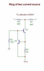
I would recommend using a higher voltage transistor for the current source. I have submitted a much more effective source as an alternative, depending on beta of the transistors the effective tail resistance can be several meg ohms. To change current levels just replace R1 with a smaller value - 33 ohms would result in roughly 20mA of current. Any transistor with VCeo 100V with a beta of 100 and an HFE of 60MHz will give good performance. Note resistance of R2 can be increased if you are using higher voltage negative rails, current flowing in Q2 should be typically > = 10% of Q1 collector current. (Not critical) In the case of a -40V rail I would probably make R2 about 22K.
Pay attention to the dissipation in transistor Q1 (about 0.8W) use a device in a TO-202 package with a heatsink.
Pay attention to the dissipation in transistor Q1 (about 0.8W) use a device in a TO-202 package with a heatsink.
Attachments
I haven't gone through and figured out how much the local DC feedback upsets the operating points of each stage to which its connected, so no comment there, other than "lotsa luck." You'll have to do a bunch of iterative calculations to get at this.
Indeed, it's a PITA, especially with step networks. To calculate voltage drop across plate load resistors, for instance, I smlply assume the plate load and feedback resotors are in parallel. It's a crude approximation but it's easy to do and reasonably accurate. Incidentally, the reason I used a step network as coupling between the 6SL7 plate and 6SN7 grid was partly to achieve the required voltage on the 6SN7 grid but also to obtain a better frequency response than I would get from capacitive coupling.
However, I don't know if the latter objective is really valid. If I go with a solid state current source, it would be easier and potentially more stable to use simple capacitive coupling. What concerns me is that I could easily exceed the maximum dissipation of the PN2222A (.43 W).
But the CS for the diff amp can be put together in a more stable and simple way. Run a resistor (R1) from one of the positive supplies to the base of the 2222. Run a resistor (R2) from the emitter of the 2222 to one of the stable negative rails. Then connect a forward-biased diode and a reverse biased 6.2V zener in series from the 2222 base to the far end of R2. (Sorry to be wordy, I'm not near my scanner at the moment).
Calculate R2 from R2 = 6.2/i, where i is the total current for the diff pair plus feedback. Calculate R1 from (Vpos-Vneg+6.8)/10i.
I understand what you're saying. [However, for the value of R1, I think you meant to say (Vpos-Vneg+6.8)/0.1i ?]
I must be careful of exceeding the max dissipation of the PN2222A and, for this reason, I might have to limit the negative rail to just a few volts.
I would recommend using a higher voltage transistor for the current source. I have submitted a much more effective source as an alternative, depending on beta of the transistors the effective tail resistance can be several meg ohms.
That's a neat-looking CCS. I guess Q2 wants to see ~0.6 v at its base and will pull down the base of Q1 if the voltage across R1 rises above this. However, if the voltage across R1 falls below 0.6v then Q2 will switch off and Q1 will then try to draw more base current through R2, which will increase its CE current and cause the voltage across R1 to increase, activating Q2 again.
I would recommend fairchild KSC2682 if you can get your hands on it. The low minimum beta of the MJE340 doesn't thrill me, and the 2682 is well specified for operation in the current region we are interested in, and on a proper heat sink can dissipate up to 8W. Try to find a transistor with a minimum beta of around 100 at less than 100mA, and try to avoid anything much over 300. Vceo should be at least 30% greater than the worst case operating voltage from collector to emitter. I like fairly high FT devices, typically something with a 60MHz rating.. What is the V- rail going to be for the CCS? As to whether or not you can use 2N2222 that depends on the negative rail, if it is much over -25V I would reconsider.
OK, I'll try to get a KSC2682.
I plan to use two ring-of-two CCSs, one for the 6SL7 with neg. rail of ~50v and the second for the 6SN7 with no neg. rail since the grids of the 6SN7 will be at about +57v owing to DC coupling that I plan to use between 6SL7 and 6SN7. Same difference, though, when it comes to the voltage the CS will see.
However, I thought maybe the voltage wouldn't really matter for Q2, since its collector will see only the Q1 b-to-e voltage + its own b-to-e voltage (total about 1.2v?) Anyway, if I'm going to go out and buy some KSC2682s, then I might as well buy some other higher voltage transistors for Q2 at the same time. My only limitation is that I'm in Jakarta and electronics items are not always easy to source. BTW, would it be OK to use the KSC2682, if I can find them, for both Q1 and Q2?
As to whether or not you can use 2N2222 that depends on the negative rail, if it is much over -25V I would reconsider
I plan to use two ring-of-two CCSs, one for the 6SL7 with neg. rail of ~50v and the second for the 6SN7 with no neg. rail since the grids of the 6SN7 will be at about +57v owing to DC coupling that I plan to use between 6SL7 and 6SN7. Same difference, though, when it comes to the voltage the CS will see.
However, I thought maybe the voltage wouldn't really matter for Q2, since its collector will see only the Q1 b-to-e voltage + its own b-to-e voltage (total about 1.2v?) Anyway, if I'm going to go out and buy some KSC2682s, then I might as well buy some other higher voltage transistors for Q2 at the same time. My only limitation is that I'm in Jakarta and electronics items are not always easy to source. BTW, would it be OK to use the KSC2682, if I can find them, for both Q1 and Q2?
- Status
- This old topic is closed. If you want to reopen this topic, contact a moderator using the "Report Post" button.
- Home
- Amplifiers
- Tubes / Valves
- Suitable operating point for 6SN7 as a differential driver ?