This thread continues the thread 30W 6L6 UL amp.
http://www.diyaudio.com/forums/showthread.php?s=&threadid=40884&pagenumber=5
I decided to make a new one because the topology has been changed to pure class A 6L6 CFB P-P amp.
Help is still needed and any comments, for everything until here are acceptable.
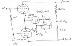
As I said to the old thread I’d like to put at the phase splitter a CCS with the second half triode of the input tube.
I have attached a schem .Do you believe that this works?
Values of R2 and R3 depend on Vb and Vg-k.
R1 depends on how much I’d like to be Vk.
How much to choose these values for good linearity of the current sink?
From the original schem I have change Va from 380V to 300V (I’m planning to use anode voltage of the P-P output stage about 300-320V) and anode loads of the phase splitter from 30K to 40K.
http://www.diyaudio.com/forums/showthread.php?s=&threadid=40884&pagenumber=5
I decided to make a new one because the topology has been changed to pure class A 6L6 CFB P-P amp.
Help is still needed and any comments, for everything until here are acceptable.
As I said to the old thread I’d like to put at the phase splitter a CCS with the second half triode of the input tube.
I have attached a schem .Do you believe that this works?
Values of R2 and R3 depend on Vb and Vg-k.
R1 depends on how much I’d like to be Vk.
How much to choose these values for good linearity of the current sink?
From the original schem I have change Va from 380V to 300V (I’m planning to use anode voltage of the P-P output stage about 300-320V) and anode loads of the phase splitter from 30K to 40K.
Attachments
Everything shown looks like it'll work... mind you a pentode is more customary than a triode for CCS, and you won't burn as much voltage. (Although I'll have to check into that. The grid voltage divider would require current drawing an analog to the screen grid requirement, while depending on the perveance (for saturation voltage), the triode may end up a reasonable CCS.)
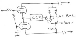
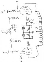
For AC balance, I would prefer balancing the plate resistors. Output stage grid leak will have little effect.
Tim
For AC balance, I would prefer balancing the plate resistors. Output stage grid leak will have little effect.
Tim
Hi Tim
I prefer to use 6SN7 because it's the other half of the first stage.I don't like to split the first 6SN7 to L+R channel.So I decided to use it as CCS of the PS.
ok I'll balance the plate resistors.
Can I put simple bourns type multiturn trimmers over there?
What kind of multiturn pots use at the cathodes of output stage?
Over there I need >2W pot,right?
Any good source?
I found at Aquablue swiss precision, for 20euro each.
resident said:Can I put simple bourns type multiturn trimmers over there?
If you only make it a fraction of the plate resistances, rather than the whole thing, multiturn will not be necessary. Tubes can't even comprehend anywhere such accuracy anyway, you'll need a live spectrum analyzer to null second harmonic distortion (which is what it will affect).
In 99% of cases, a balance isn't necessary, though along with independent fixed bias, it will allow using completely mismatched output tubes.
What kind of multiturn pots use at the cathodes of output stage?
Over there I need >2W pot,right?
Any good source?
I found at Aquablue swiss precision, for 20euro each.
::blink::
No need for a $20 ANYTHING if you ask me...
In either case, whatever voltage or current present. Ohm's law is your friend.
Tim
What do you mean with fraction?If you only make it a fraction of the plate resistances, rather than the whole thing, multiturn will not be necessary.
Aren’t self bias circuits more stable than fixed bias?though along with independent fixed bias, it will allow using completely mismatched output tubes.
With a good choice of cathode resistors (value), I can match them with self bias,too.
That’s why I decided to use pots. But I think, I’ll use Ohm’s law.
")
resident said:
What do you mean with fraction?
Say each tube of the LTP needs 56k ohms. You could use a 20k potentiometer, which at middle would give 10k on either side, allowing you to use 47k plate resistors instead (47+10 = 57, very close to the required value). That would be about one fifth, as opposed to using a whole: you could use a 100k trimmer for both purposes.
Aren’t self bias circuits more stable than fixed bias?
Uh, yes...but that has nothing to do with this.
Tim
Hi Tim,

I'm thinking to use a negative HT rail (-150V or -170V )at the lower end of the phase splitter-CCS to achieve about 450V total!
What do you say??Much moooore headroom!
About trim pots.
Ohm's law again and again.
Thank you for the idea.Even at the phase splitter.
Also,I don't think CFB output stages needs an ideal matched tubes.I'm not planning to use too different tubes.A pair of SV6L6 svetlana at each channel should not be so unmatched.
The negative rail for the cathode side of the current source will be NECESSARY so that you can run the input signal referenced to 0V.
That is to get enough voltage for the current source tube to work with.
Personally I would save the 1/2 6sn7 for a function further down the audio chain and use J-FET, MOSFET or Biplolar Transistor (Cascoded) for the current source. That way you can get very high AC impedance which is flat across a wide frequency with as little as 12V negative supply.
If you must use the triode as a current source there are 2 golden rules which will affect how much -ve voltage you need.
Rule 1) Keep the cathode resisitor high as possible (this will keep Output Impedance High).
Rule 2 - as a result of Rule 1 (largish voltage drop across the big cathode resitor) keep the Grid voltage high with respect to the negative rail and make sure that the grid voltage is nailed down tight (that is decent amount of current in the voltage divider and bypassed well OR even feed the grid from a Solid State regulator - LM317 or similar) . This advise comes to you curtesy of the Allen Wright "Tube Preamp CookBook - I've just copied it here BUT it makes good sense.
Cheers,
Ian
- Status
- This old topic is closed. If you want to reopen this topic, contact a moderator using the "Report Post" button.
- Home
- Amplifiers
- Tubes / Valves
- 6L6 class A P-P CFB amp