
Hi,
It works only with the preceeding stage and is taken originally from the WE 91 Amp, often seemingly without understanding. It "bootstrappes" the limited value cathode bypass capacitor to the grid, so it does not introduce local degeneration at low frequencies.
The driving stage must have very high output impedance for this to work, the coupling capacitor value also plays into this.
Ciao T
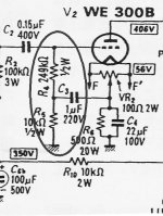
I saw some 300B self-bias SE circuit that the cathode voltage is feedback to the grid via some potential divider (R4,R5, C3), would anyone tell me the operation theory?
It works only with the preceeding stage and is taken originally from the WE 91 Amp, often seemingly without understanding. It "bootstrappes" the limited value cathode bypass capacitor to the grid, so it does not introduce local degeneration at low frequencies.
The driving stage must have very high output impedance for this to work, the coupling capacitor value also plays into this.
Ciao T
Hi,
It works only with the preceeding stage and is taken originally from the WE 91 Amp, often seemingly without understanding. It "bootstrappes" the limited value cathode bypass capacitor to the grid, so it does not introduce local degeneration at low frequencies.
The driving stage must have very high output impedance for this to work, the coupling capacitor value also plays into this.
Ciao T
Which was the case since the preceding stage was a pentode connected pentode with a 100K plate load resistor.. Also I believe the cathode bypass cap in a WE91A was much smaller than in the example shown above. (I can't make out the value in the schematic linked to below, and my paper copy is in a filing cabinet in the garage. (Too cold today!): http://www.nutshellhifi.com/library/schematics/we91a.jpg
Hi,
It is possible that this is indeed the case for the full schematic of which an excerpt was posted above, however i would not suggest so with great confidence.
There where a few versions, one I have at hand for the 91B suggests it was 16uF, which is very similar to the 22uF shown above.
Ciao T
Which was the case since the preceding stage was a pentode connected pentode with a 100K plate load resistor..
It is possible that this is indeed the case for the full schematic of which an excerpt was posted above, however i would not suggest so with great confidence.
Also I believe the cathode bypass cap in a WE91A was much smaller than in the example shown above.[/url]
There where a few versions, one I have at hand for the 91B suggests it was 16uF, which is very similar to the 22uF shown above.
Ciao T
- Status
- This old topic is closed. If you want to reopen this topic, contact a moderator using the "Report Post" button.