Hi, I have recently been trying to buid a circuit that will allow me to swicth a signal of around 1700V peak to peak into a mainly capactive load as part of a university project.
The only problem so far is that as soon as my output gets much beyond about 700v peak to peak (using a transistor switch to drive a step up transformer; about 1:10 turns ratio) the transistor goes pop (probably because of the back EMf formed by the transformer when the MOSFET switches off).
I am considering two aproaches to solving the problem, firstly I will simply try and build something which will keep the voltage accross the MOSFEt to less than 200V (using a zenner diode, or VDR e.t.c.).
The second thing that I was considering was to use a valve circuit in place of the MOSFET one I am currently using. However, I don't know a lot about valves, so I was hoping some body here would be able to point me in some sort of direction towards a possible circuit design for this type of device, or at least tell me if I am being a little hopefull in getting this sort of performance in a circuit of this type.
Anyway, if anyone has anyinformation that may be useful, I would be most greatful to hear about it.
Andrew.
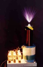
Sounds like what you want is a vacuum tube tesla coil. Is the capacitive load steady or does the capacitance change during the experiment? If steady you can make an air core HV resonator that will feed this capacitive load, the two forming a parallel LC circuit (or series depending on your point of view). You will need to build an RF power oscillator with a vaccum tube (triode is best). A tank coil from the vacuum tube oscillator can magnetically couple to the HV resonator. You also wind a grid 'tickler' coil in next to the tank coil to supply positive feedback to make the oscillator work. If you can tolerate RF that comes on and off with a 60 Hz sinewave pulse train with 50% dead air between pulses you can use unfiltered AC on the oscillator plate supply. If you need ripple free RF CW you make a filtered HVDC power supply. There are many suitable triodes available. How much power do you need, do you know? How critical is the absolute frequency and the stability of the frequency? Does it have to be phase locked to another device?
Here is a picture of what I am speaking about. This coil system uses four 811A triodes operating in a self feedback RF power oscillator at a much lower frequency of several hundred KHz. You can see the white plate tank coil, the green grid tickler coil underneath both wound on a PVC pipe former, and a HV resonator inserted inside the tank to develop the high voltage RF. This unit is producing about 50-75 kV into the corona load with a little over one horsepower of RF.
Here is a picture of what I am speaking about. This coil system uses four 811A triodes operating in a self feedback RF power oscillator at a much lower frequency of several hundred KHz. You can see the white plate tank coil, the green grid tickler coil underneath both wound on a PVC pipe former, and a HV resonator inserted inside the tank to develop the high voltage RF. This unit is producing about 50-75 kV into the corona load with a little over one horsepower of RF.

bigparsnip said:Hi, I have recently been trying to buid a circuit that will allow me to swicth a signal of around 1700V peak to peak into a mainly capactive load as part of a university project.
you know, for a country which invented RADAR...
a horizontal sweep tube won't handle 1700 V -- there were only one or two which were rated for Plate voltage >450V (I know this flavor well, having built several ham transmitters in the 1960's)., nor will the 807 and the the 811 mentioned has a max plate voltage of 1500V
You could use a 8068 if you can find them -- octal base, anode cap, these were used in high voltage tube regulated power supplies for the US Dept of Defense. If you find them, let me know !
the triodes 3-100, 3-150, 572, 810, V70 and tetrodes PL-177, 813, 4-125, 4X150, 4CX250
if using any of the aforementioned you need a really robust filament transformer...
you are probably better of stringing together some beefy HEXFET's together in series -- grab urself a copy of Horowitz and Hill in the University Library and you will see an example.
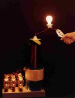
Thanx! Here is a neat parlour trick one can do with such a device under the guidance of a trained professional. There is no hidden wire up the wrist. The man's hand and body are passing all the current used to illuminate the standard household 40 watt incandescent light bulb. Inexperienced amateurs, do NOT try this yourself. Such energy is lethal under normal conditions.
Bigparsnip,
I can email you two jpg. images of a construction article which can be used as a tutorial. PM me a request if you desire with a real email address that can receive it.
Bigparsnip,
I can email you two jpg. images of a construction article which can be used as a tutorial. PM me a request if you desire with a real email address that can receive it.
Attachments
Re: Re: 2MHz, High voltage source?
Peak voltage > 6.6kV.
<Snip remaining 3 paragraphs>
Tim
jackinnj said:a horizontal sweep tube won't handle 1700 V
Peak voltage > 6.6kV.
<Snip remaining 3 paragraphs>
Tim
You could also build a HVDC power supply from a domestic microwave oven power transformer to give you 1700 VDC by reducing the primary voltage a bit. With a suitable series load resistor or inductor you could use a shunt modulator tube across the capacitive load. A color TV beam triode like a 6HV5 might work out for you. You could drive the tube from a control oscillator. You could choose the series L to resonate at 2 MHz with the load capacitance to greatly improve efficiency. In this case the B+ supply could be less than 1700 VDC depending on circuit Q.
You could use try using a thyratron or a HV SCR to switch your high voltage. To generate a low current HV source, try this kit:
http://www.electrokits.com/electronic-kits/miscellaneous/73.htm
Larry
http://www.electrokits.com/electronic-kits/miscellaneous/73.htm
Larry
here's a high voltage HEXFET series string -- if you are hard-switching at 2MHz you're going to generate plenty of harmonics so you should use a choke or bandpass filter on the output -- since you are in the UK, perhaps an RSGB Handbook would be helpful. (A spectrum analyzer would help too !)
Kepco manufacturers something like this as a substitute for the 8068 tubes used in their BHK Power Supplies.
1.7kV is nothing to sneeze at -- make sure that you are using HV wire, if using a PCB you have to make sure that the distance between traces prevents arc-over. this is not trivial at all -- even close proximity of your skin to a HV trace (depending upon the humidity) can result in a nasty shock.
Attachments
Hi, thanks for all of the replies so far (it's given me somewhere to try and start looking through the myriad of information that seems to revolve around tube circuits) but I guess I should have been a little clearer on what I would like to be doing.
Basicaly, I am trying to drive an electric field across a gap of around 500 microns (about 20 thou for those wo dont't like metric) to act as a filter for some gasses passing between the plates. I'm not entierly sure of the exact shape or frequency needed for the wave yet, just that it should be between 1 and 2 MHz in frequency, with a duty cycle of between 20 and 30 percent (based around a square wave rather than a sine wave, so I guess overall bandwidth will need to be higher than 2MHz).
So, in this case power oscilators will probably not work (due to the duty cycle variations), however, it should be possible to make a partly resonant circuit (I think) to reduce the overall power that will be needed to drive it.
Also, while I'm here does anyone know a good site about winding high frequency transformers, as I'm sure the ones I'm using for the MOSFET switching are far from ideal.
Andrew.
Edit: oh, one more thing the load will be a steady 1.6pF (assuming the gasses all have permiabilities close to that of air)
now that we know what you are trying to do:
http://members.misty.com/don/laserhpd.htm
there are also DIY electrophoresis power supplies which you can google.
there are a lot of flyback circuits which will work -- you could also repurpose a used (ancient) BW TV or an oscilloscope.
reminds me of the 1960's and 1970's when you had to build everything yourself.
If you want *total* control, you can do a class A (won't be bad, depending on current draw and slew rate required) with a tube like this:
http://www.mif.pg.gda.pl/homepages/frank/sheets/093/6/6CD6GA.pdf
(There's a whole slew of them, 1970s era tubes got Vsat down around 50V at 1A, EL509/6KG6 for instance.)
An inductive or resistive load should do it, depending on your need. Such a choke load will be a custom though.
Tim
http://www.mif.pg.gda.pl/homepages/frank/sheets/093/6/6CD6GA.pdf
(There's a whole slew of them, 1970s era tubes got Vsat down around 50V at 1A, EL509/6KG6 for instance.)
An inductive or resistive load should do it, depending on your need. Such a choke load will be a custom though.
Tim
Here is a link to a guy that built a cyclotron. His power supply could supply 1,300 Volts at 2.2MHz at 400 Watts. He used 2-811A in PP.
http://www-personal.umich.edu/~mrniell/cyc2.html
The schematic:
http://www-personal.umich.edu/~mrniell/schematic.jpg
Larry
http://www-personal.umich.edu/~mrniell/cyc2.html
The schematic:
http://www-personal.umich.edu/~mrniell/schematic.jpg
Larry
Well, I have been doing more hunting around, and seem to have found something which looks almost perfect for what I want to be doing with the set up (you can read the paper on it and see the design here) The only thing with it is that it will in it's current form produce a wave which is entierly symetric, where as I need one wich has around a 30% duty cycle. So, what I was wondering (as I dont' have a huge amount of experience in this area) is if I can effect the symetry of the output by causing an imbalence in the resonant components to get my asymetric output. What I had though about doing was to offset the center tap on the inductor and using different value coupling capacitors on the output as well. So, if anyone could tell me if I have any chance of success before I go and try to order the parts, it would be much appreciated.
- Status
- This old topic is closed. If you want to reopen this topic, contact a moderator using the "Report Post" button.
- Home
- Amplifiers
- Tubes / Valves
- 2MHz, High voltage source?