So, instead of insulating each problem and solving it as it occurs perfably by the most approriate methode (which is a short feedback loop between Output Stage and Driver IMHO) we have maximised each problem to appear on the secondary of the output transformer and after having royally screwed up the signal we loop some negative feedback in to see if can somehow pull out the lumped mess and straighten it again.
I did not mean something else.
It seems to me that it's no a good idea to releive entierly on global
NFB, since, as you point, this single loop has to cancel all acumulated
errors in the whole amp.
It's a funny experience to look at the shape of the signal on the grid(s)
of the output stage with such a design. It can look very assymetric and
causes output tubes bias shift, link caps being charged by the grid current
even if the outout stage was not intended to do so !!!
Thus the driver already has to supply this kind of "predistorded" level.
The output stage MUST include some local NFB, specially if uses penthodes or tetrodes.
A global loop may be added to reduce Zo if needed.
Yves.
KYW, I am not that surprised that you consider 90% of all designs old and new ones to be crap but I think you are a bit inconsistent.
First you say
Then you refer to a lot of designs where it has been considered beneficial to use local feedback and global feedback including the OT can you clarify what you mean? are these designs also crap? Are only designs where the OT are not at all included in the feedback chain good designs?
Although local feedback can compensate for unlinearities and reduce output impedance it is not as effective as using global feedback including the OT. Distortion from the transformer, (mostly 3rd and 5th order) and output impedance is not directly dependant on source impedance.
If source impedance is reduced to 1/4 the distortion is reduced to roughly 1/3 and if the source impedance is reduced to 1/10 the distortion is reduced to roughly 1/7, these figures are valid for a case where the transformer is optimised for the new source impedance. If only the source impedance is lowered but the transformer is not changed, the reduction in distortion is even less, for 1/4 source impedance distortion will be lowered to 0.4 of what it was. However global feedback would reduce the distortion as much as the amount of feedback.
For reduction of output impedance, (improving DF) changing source impedance make no difference if the OT is optimised for the new source impedance, if the same OT is used the output impedance is reduced, if source impedance is reduced to 1/4 output impedance is reduced to 0.46 of what it was. Also in this case global feedback is more effective and 4 times global feedback will lower the output impedance to 1/4 of what it was.
(All calculations based on a case where primary impedance is 4000 ohm, secondary load 8 0hm and DCR 0.05 of primary resp secondary impedance)
I am well aware of that there are other benefits of lowering source impedance as it will be easier to make a transformer with wider bandwidth but this together with the above results indicate that a mix of local and global feedback is the optimum way to go, maybe not a surprise as this is what many designers both old and new have used / are using, (for instance Knapp and Kiebert that I referred to and many others).
For the original question on how to improve DF in an existing amplifier without changing OT clearly the most effective way is to use global feedback including the OT in the loop. As your output transformers are designed for 3500 primary impedance it is probably adviceable to first lower the source impedance to 1/2 by local feedback and then apply global feedback, using the transformer to reflect a load of 7kohm when it is designed for 3.5kohm is not optimum as the primary inductance will be too low for the higher impedance, result being loss of low frequencies. I dont think you have to worry about instability if you keep the amount of global feedback reasonable, try to increase feedback until you get oscillations or instability and then back of required amount, you can also introduce phase compensating networks in the amplifier if you want to apply higher amount of global feedback but that requires a bit more of measurements and calculations.
Regards Hans
First you say
In fact, I'd go as far as saying that to apply loop feedback from the secondary of an output transformer must be counted as monumentally stupid, compared to leaving the output transformer outside the loop....
Then you refer to a lot of designs where it has been considered beneficial to use local feedback and global feedback including the OT can you clarify what you mean? are these designs also crap? Are only designs where the OT are not at all included in the feedback chain good designs?
Although local feedback can compensate for unlinearities and reduce output impedance it is not as effective as using global feedback including the OT. Distortion from the transformer, (mostly 3rd and 5th order) and output impedance is not directly dependant on source impedance.
If source impedance is reduced to 1/4 the distortion is reduced to roughly 1/3 and if the source impedance is reduced to 1/10 the distortion is reduced to roughly 1/7, these figures are valid for a case where the transformer is optimised for the new source impedance. If only the source impedance is lowered but the transformer is not changed, the reduction in distortion is even less, for 1/4 source impedance distortion will be lowered to 0.4 of what it was. However global feedback would reduce the distortion as much as the amount of feedback.
For reduction of output impedance, (improving DF) changing source impedance make no difference if the OT is optimised for the new source impedance, if the same OT is used the output impedance is reduced, if source impedance is reduced to 1/4 output impedance is reduced to 0.46 of what it was. Also in this case global feedback is more effective and 4 times global feedback will lower the output impedance to 1/4 of what it was.
(All calculations based on a case where primary impedance is 4000 ohm, secondary load 8 0hm and DCR 0.05 of primary resp secondary impedance)
I am well aware of that there are other benefits of lowering source impedance as it will be easier to make a transformer with wider bandwidth but this together with the above results indicate that a mix of local and global feedback is the optimum way to go, maybe not a surprise as this is what many designers both old and new have used / are using, (for instance Knapp and Kiebert that I referred to and many others).
For the original question on how to improve DF in an existing amplifier without changing OT clearly the most effective way is to use global feedback including the OT in the loop. As your output transformers are designed for 3500 primary impedance it is probably adviceable to first lower the source impedance to 1/2 by local feedback and then apply global feedback, using the transformer to reflect a load of 7kohm when it is designed for 3.5kohm is not optimum as the primary inductance will be too low for the higher impedance, result being loss of low frequencies. I dont think you have to worry about instability if you keep the amount of global feedback reasonable, try to increase feedback until you get oscillations or instability and then back of required amount, you can also introduce phase compensating networks in the amplifier if you want to apply higher amount of global feedback but that requires a bit more of measurements and calculations.
Regards Hans
Konnichiwa,
It shall be better say that circuits that use only one long feedback loop are rather not so good. Designs using multiple inner feedback loops and only a "notional" outer loop tend to be quite good. The more the NFB is shifted from inner loops to outer loop the worse.
Hmmm. It is actually very effective.
Hmmm. Measurements I have done have shown a pretty direct relation between source impedance and distortion in transformers. At any extent, most transformers will show any material distortion only at low frequencies and high levels.
I am not sure I follow your reasoning. Have you actually taken a simple Output transformer and made the measurements?
While that is true, as noted before, the transformer distortion becomes significant only at low frequencies and even there it will remain fairly low if you ensure to avoid going too close to saturation.
That is so obviously incorrect, that it makes me question your sources.
Let's take a real example. We have a conventional 3K5:8 Output Transformer with 120 ohm primary DCR and 0.2 ohm secondary DCR. The net resistance introduced by the OPT is around 0.5R.
Now we take a Triode EL-34 PP Stage with around 2K output impedance driving this. Without NFB we have around 5 Ohm output impedance in Class A operation. If we apply 12db feedback in a loop including the OPT we get 1.25 Ohm effective output impedance, if we take feedback from the anodes of the EL-34 PP Stage our output impedance we get 1.65 Ohm.
So, applying 12db NFB in the inner loop reduces our output impedance to 0.33 times of that present open loop WITHOUT ANY changes to the OPT, applying 12db NFB in the Outer loop gets the nominal 0.25 times of the output impedance under open loop conditions.
Yes, there is a difference, if the DCR is lower than my suggestions (which are based on a real transformer) it will be even less.
I disagree. The long outer NFB loop will invariably be subject to drastic changes of feedback factor with frequency which indicates phase margin problems and thus transient problems absent if that feedback loop is avoided.
All in all I retain, a given amount of feedback is placed best in an inner loop excluding the output transformer if subjective sound quality, load tolerance and stability are of concern MORE than meaningless testbench numbers.
Especially when weighted distortion measurements are applied (as suggested ages ago by Crowhurst, Shorter et al and recently revived) the superiority of that approach becomes readily aparent. The only price paid is a modest increase in output impedance from the DCR losses of the output transformer, which in reality is nothing to worry about.
As you mention Kiebert, you are no doubt aware that he used on outer loop for his own most critical (in terms of sound quality - like his cutting head amplifiers) Designs?
Not neccesarily. The OPT may introduce enough stability problems to force you to reduce the NFB applied to avoid instability. Then you are left at that (or you have to start adding inner loops).
I found that I can apply a lot more NFB in the inner loop from the Output stages anodes than when including the output transformer, both in terms of stability AND of avoiding some of the obvious sonic problems introduced by using a system that attempts to fix errors after they have already happened (Negative feedback).
The result is IN REALITY that the resulting Amplifier has LOWER DISTORTION and LOWER OUTPUT IMPEDANCE as one using the same Output Transformer and a global loop in the traditional application.
And that was my point in the first place.
Sayonara
tubetvr said:Then you refer to a lot of designs where it has been considered beneficial to use local feedback and global feedback including the OT can you clarify what you mean? are these designs also crap? Are only designs where the OT are not at all included in the feedback chain good designs?
It shall be better say that circuits that use only one long feedback loop are rather not so good. Designs using multiple inner feedback loops and only a "notional" outer loop tend to be quite good. The more the NFB is shifted from inner loops to outer loop the worse.
tubetvr said:Although local feedback can compensate for unlinearities and reduce output impedance it is not as effective as using global feedback including the OT.
Hmmm. It is actually very effective.
tubetvr said:Distortion from the transformer, (mostly 3rd and 5th order) and output impedance is not directly dependant on source impedance.
Hmmm. Measurements I have done have shown a pretty direct relation between source impedance and distortion in transformers. At any extent, most transformers will show any material distortion only at low frequencies and high levels.
tubetvr said:If source impedance is reduced to 1/4 the distortion is reduced to roughly 1/3 and if the source impedance is reduced to 1/10 the distortion is reduced to roughly 1/7, these figures are valid for a case where the transformer is optimised for the new source impedance. If only the source impedance is lowered but the transformer is not changed, the reduction in distortion is even less, for 1/4 source impedance distortion will be lowered to 0.4 of what it was.
I am not sure I follow your reasoning. Have you actually taken a simple Output transformer and made the measurements?
tubetvr said:However global feedback would reduce the distortion as much as the amount of feedback.
While that is true, as noted before, the transformer distortion becomes significant only at low frequencies and even there it will remain fairly low if you ensure to avoid going too close to saturation.
tubetvr said:For reduction of output impedance, (improving DF) changing source impedance make no difference if the OT is optimised for the new source impedance, if the same OT is used the output impedance is reduced, if source impedance is reduced to 1/4 output impedance is reduced to 0.46 of what it was. Also in this case global feedback is more effective and 4 times global feedback will lower the output impedance to 1/4 of what it was.
That is so obviously incorrect, that it makes me question your sources.
Let's take a real example. We have a conventional 3K5:8 Output Transformer with 120 ohm primary DCR and 0.2 ohm secondary DCR. The net resistance introduced by the OPT is around 0.5R.
Now we take a Triode EL-34 PP Stage with around 2K output impedance driving this. Without NFB we have around 5 Ohm output impedance in Class A operation. If we apply 12db feedback in a loop including the OPT we get 1.25 Ohm effective output impedance, if we take feedback from the anodes of the EL-34 PP Stage our output impedance we get 1.65 Ohm.
So, applying 12db NFB in the inner loop reduces our output impedance to 0.33 times of that present open loop WITHOUT ANY changes to the OPT, applying 12db NFB in the Outer loop gets the nominal 0.25 times of the output impedance under open loop conditions.
Yes, there is a difference, if the DCR is lower than my suggestions (which are based on a real transformer) it will be even less.
tubetvr said:I am well aware of that there are other benefits of lowering source impedance as it will be easier to make a transformer with wider bandwidth but this together with the above results indicate that a mix of local and global feedback is the optimum way to go,
I disagree. The long outer NFB loop will invariably be subject to drastic changes of feedback factor with frequency which indicates phase margin problems and thus transient problems absent if that feedback loop is avoided.
All in all I retain, a given amount of feedback is placed best in an inner loop excluding the output transformer if subjective sound quality, load tolerance and stability are of concern MORE than meaningless testbench numbers.
Especially when weighted distortion measurements are applied (as suggested ages ago by Crowhurst, Shorter et al and recently revived) the superiority of that approach becomes readily aparent. The only price paid is a modest increase in output impedance from the DCR losses of the output transformer, which in reality is nothing to worry about.
tubetvr said:maybe not a surprise as this is what many designers both old and new have used / are using, (for instance Knapp and Kiebert that I referred to and many others).
As you mention Kiebert, you are no doubt aware that he used on outer loop for his own most critical (in terms of sound quality - like his cutting head amplifiers) Designs?
tubetvr said:For the original question on how to improve DF in an existing amplifier without changing OT clearly the most effective way is to use global feedback including the OT in the loop.
Not neccesarily. The OPT may introduce enough stability problems to force you to reduce the NFB applied to avoid instability. Then you are left at that (or you have to start adding inner loops).
I found that I can apply a lot more NFB in the inner loop from the Output stages anodes than when including the output transformer, both in terms of stability AND of avoiding some of the obvious sonic problems introduced by using a system that attempts to fix errors after they have already happened (Negative feedback).
The result is IN REALITY that the resulting Amplifier has LOWER DISTORTION and LOWER OUTPUT IMPEDANCE as one using the same Output Transformer and a global loop in the traditional application.
And that was my point in the first place.
Sayonara
KYW,
I think what you are writing i still inconsistent, it is not clear for me, (and can't be for anyone else either) if you approve of designs using a mix of local and global feedback including the OT in the global loop or if you disapprove completely of including the OT in the loop.
First you write,
Then you say regarding amplifiers where the OT are not included in the loop,
Can you care to explain? Do you approve of designs using local and global loops including the OT as seems to be the choice of most designers or do you say that only your way excluding the OT is the way to go, and subsequently that most other designers are wrong?
Some comments to what you wrote regarding some points in my reply
Re effeciency of global versus local feedback I wrote
I haven't questioned the efficency of local feedback, I have only said that it is less efficient than global in some ways, (which you actually confirm)
Regarding my calculations of effect on source impedance on distortion in output transformers you have some comments, let me reply to all of these here.
Distortion in an OT is not directly related to the source impedance but for any given transformer directly related to the parallell combination of (the sum of primary impedance and primary DCR) and (the sum of the secondary load and secondary resistance reflected to the primary).
This means that when the source impedance is lowered distortion is lowered but not as much as the source impedance is lowered. If this was not the case a transformer would be distortion free when fed from a 0 source impedance which it is not. The formulas for how to calculate distortion can be found here http://www2.gol.com/users/tube/papersindex.html on pages 12 and 13, I have copied this from a text found in "Radio engineering handbook" by ITT but the original source is from another book, as I don't have access to the ITT book right now, (it is in my office) I can't give information about the original source until sometime later, however the basic formula for how to calculate distortion in a transformer can be found in many other texts.
I have access to measurements on real output transformers confirming that the formula give a correct result with respect to sensitivity to source impedance as to be expected.
Regarding your comments regarding output impedance and relation to source impedance you are actually confirming my results by your own example, the figures I have given are correct given the transformer data I also gave which by the way is based on a real transformer, agreed the quality of that one is lower than the one in your example but it is not unusually bad.
What could be interesting to notice is that the efficiency of lowering the source impedance is less when the transformer quality is lower, i.e. when DCR is high, this would indicate that including the transformer in the global feedback loop is more of value when the transformer is of dubious quality.
Interesting comment, do you really believe that any amount of feedback including a transformer in the loop will always introduce phase margin problems? Is it not dependant on the transformer quality, the number of poles and their values at other points in the amplifier and of course the amount of feedback?
I think you with this refer to the Kiebert amplifier for cutting heads that doesn't contain an outer loop? as described here http://www.clarisonus.com/Archives/Amp_Design/Kiebert.pdf in fig 19 on page 40, yes I see that this amplifier doesn't include the OT in the loop but I also notice that in all other described amplifiers the OT is included in the loop, (but according to you these designs are bad).
I wrote earlier
And your comment is:
Ah! Now I see, you believe that I argue for using only outer loops including the OT and not use any internal loops at all? Where did you got that from? I have only said that including the OT in a global feedback loop is more efficient with respect to lowering the output impedance and to lower transformer introduced distortion than to use the same amount of feedback for lowering the source impedance but I never argued for that this should be the only applied feedback, on the contrary I have given references to several amplifier designers that have used multiple loops as I also believe is the optimum way.
I didn't think that you where an advocate for large amount of feedback? Is it not enough with the minimum amount of feedback that gives you the desired result? And is it not then the optimum way to apply feedback in the most efficient way which is to use several feedback loops where one include the OT? At least this is what most designers current and past have found.
Regards Hans
I think what you are writing i still inconsistent, it is not clear for me, (and can't be for anyone else either) if you approve of designs using a mix of local and global feedback including the OT in the global loop or if you disapprove completely of including the OT in the loop.
First you write,
Designs using multiple inner feedback loops and only a "notional" outer loop tend to be quite good.
Then you say regarding amplifiers where the OT are not included in the loop,
The result is IN REALITY that the resulting Amplifier has LOWER DISTORTION and LOWER OUTPUT IMPEDANCE as one using the same Output Transformer and a global loop in the traditional application.
Can you care to explain? Do you approve of designs using local and global loops including the OT as seems to be the choice of most designers or do you say that only your way excluding the OT is the way to go, and subsequently that most other designers are wrong?
Some comments to what you wrote regarding some points in my reply
Re effeciency of global versus local feedback I wrote
You commentedAlthough local feedback can compensate for unlinearities and reduce output impedance it is not as effective as using global feedback including the OT.
Hmmm. It is actually very effective.
I haven't questioned the efficency of local feedback, I have only said that it is less efficient than global in some ways, (which you actually confirm)
Regarding my calculations of effect on source impedance on distortion in output transformers you have some comments, let me reply to all of these here.
Distortion in an OT is not directly related to the source impedance but for any given transformer directly related to the parallell combination of (the sum of primary impedance and primary DCR) and (the sum of the secondary load and secondary resistance reflected to the primary).
This means that when the source impedance is lowered distortion is lowered but not as much as the source impedance is lowered. If this was not the case a transformer would be distortion free when fed from a 0 source impedance which it is not. The formulas for how to calculate distortion can be found here http://www2.gol.com/users/tube/papersindex.html on pages 12 and 13, I have copied this from a text found in "Radio engineering handbook" by ITT but the original source is from another book, as I don't have access to the ITT book right now, (it is in my office) I can't give information about the original source until sometime later, however the basic formula for how to calculate distortion in a transformer can be found in many other texts.
I have access to measurements on real output transformers confirming that the formula give a correct result with respect to sensitivity to source impedance as to be expected.
Regarding your comments regarding output impedance and relation to source impedance you are actually confirming my results by your own example, the figures I have given are correct given the transformer data I also gave which by the way is based on a real transformer, agreed the quality of that one is lower than the one in your example but it is not unusually bad.
What could be interesting to notice is that the efficiency of lowering the source impedance is less when the transformer quality is lower, i.e. when DCR is high, this would indicate that including the transformer in the global feedback loop is more of value when the transformer is of dubious quality.
The long outer NFB loop will invariably be subject to drastic changes of feedback factor with frequency which indicates phase margin problems and thus transient problems absent if that feedback loop is avoided.
Interesting comment, do you really believe that any amount of feedback including a transformer in the loop will always introduce phase margin problems? Is it not dependant on the transformer quality, the number of poles and their values at other points in the amplifier and of course the amount of feedback?
As you mention Kiebert, you are no doubt aware that he used on outer loop for his own most critical (in terms of sound quality - like his cutting head amplifiers) Designs?
I think you with this refer to the Kiebert amplifier for cutting heads that doesn't contain an outer loop? as described here http://www.clarisonus.com/Archives/Amp_Design/Kiebert.pdf in fig 19 on page 40, yes I see that this amplifier doesn't include the OT in the loop but I also notice that in all other described amplifiers the OT is included in the loop, (but according to you these designs are bad).
I wrote earlier
For the original question on how to improve DF in an existing amplifier without changing OT clearly the most effective way is to use global feedback including the OT in the loop.
And your comment is:
Not neccesarily. The OPT may introduce enough stability problems to force you to reduce the NFB applied to avoid instability. Then you are left at that (or you have to start adding inner loops).
Ah! Now I see, you believe that I argue for using only outer loops including the OT and not use any internal loops at all? Where did you got that from? I have only said that including the OT in a global feedback loop is more efficient with respect to lowering the output impedance and to lower transformer introduced distortion than to use the same amount of feedback for lowering the source impedance but I never argued for that this should be the only applied feedback, on the contrary I have given references to several amplifier designers that have used multiple loops as I also believe is the optimum way.
I found that I can apply a lot more NFB in the inner loop from the Output stages anodes than when including the output transformer, both in terms of stability AND of avoiding some of the obvious sonic problems introduced by using a system that attempts to fix errors after they have already happened (Negative feedback).
The result is IN REALITY that the resulting Amplifier has LOWER DISTORTION and LOWER OUTPUT IMPEDANCE as one using the same Output Transformer and a global loop in the traditional application.
I didn't think that you where an advocate for large amount of feedback? Is it not enough with the minimum amount of feedback that gives you the desired result? And is it not then the optimum way to apply feedback in the most efficient way which is to use several feedback loops where one include the OT? At least this is what most designers current and past have found.
Regards Hans
Konnnichiwa,
I approve of using as short feedback loops as possible and if neccesary using multiple neted loops.
However, I take SEVERE issue with the statement that "most designers choose designs using local and global loops including the OT". Most designers (solid state and valve) choose just one outer loop, in Valve circuits including the Output transformers.
I suggest using only one outer NFB loop as commonly done is monumentally stupid. Other applications have to stand on their own merit.
I find that if the inner loop is optimised to be the main loop it usually results in better subjective and objective performance than using outer and inner loop, but that position is admittedly debatable, as is what "good objective performance" consists of.
For example, to me reducing as much as possible high order harmonics is part of "good objective performance". Due to the distortion multiplying effect of multiple stages and of inverse feedback (distortion of distortion of distortion send back to the input stage where it is distorted.....ad infinitvm) it would seem that the more stages are inlcuded in a feedback loop the worse the objective performance as I see it.
!!??
In our amplifier we have a given load and a given set of copper losses.
If we now reduce the Source Impedance feeding the transformer the distortion is reduced at high source impedance values directly proportionatly to the source impedance, at source impedances approaching the copper losses (DCR) of the transformer the distortion approaches asymtotically a given minimimum determined by the copper losses (DCR) of the transformer.
If we applied a negative source impedance equal to the copper losses (DCR) we could in theory kill all distortion in the transformer.
I thought that much was understood commonly. Do you disagree?
The transformer is (nearly) distortion free when fed from a negative impedance compensating it's copper losses, in which case we gat in the magnetic terms a "0 Ohm" source.
And all these formulas show at best a first approximation but poor correlation in reality, as they use models simplified beyound the degree at which they are usefull in practice. Remember, this all goes back to times when you did not even have electronic pocket calculators. The Formulas you cite only work well in a fairly narrow range of source vs nominal primary impedance.
Do some measurements if you like, at "extreme" values of the source impedance you will find very poor correlation with these formulas.
I have done measurements myself which fail to do so.
Okay, shall we re-do the calculation based on your 0.05 Ohm effective copper loss in the secondary?
Here your originally posited thesis:
Lets consider a pair of Pentode wired EL34 at 10K and a pair of Pentode wired EL34 with 12db NFB from the Anodes as implemented by me at 2K5 source impedance.
These are realistic levels of impedance and shall confirm if a four fold (1/4 or 0.25) reduction in source impedance lead to a only about 2 fold (0.46) reduction in output impedance after the output transformer, shall we?
The output impedance with the Pentode is 10,000/(4000/8) + 0.05 or 20.05 Ohm. Our Triode Stage output Impedance is 2,500/(4000/8) + 0.05 or 5.05 Ohm.
The ratio between 20.05 and 5.05 is 0.2518. This is very close to the theoretically ideal 0.25 ratio and miles off the 0.46 ratio you suggest. Far from supporting your thesis, my example actually disproves it.
Sadly, such "dubious quality" transformers often also have poor HF performance, severely limiting the amount of inverse feedback applicbale, so that once all the NFB is applied in the outer loop that can be applied without compromising stability we may still find our output impedance higher than if we had much more inverse feedback in a short inner loop.
Of course, we may combine inner loops and outer loops, but the differences will rather disappear into six of one, halve a dozend of the other, given an otherwise identical circuit. And the distortion multiplying facilities of the outer feedback loop will still monkey with our distortion spectrum severely to the detriment of audiblity of the distortion.
Not ANY amount. However ANY amount to be really usefull will do.
Absolutely. In practice the Output Transformer will usually form the dominat pole and be the dominant cause of phaseshift. The phasemargin will become quite samll at fairly low frequenies for usefull degrees of inverse feedback (around 20db) in fact neccesaitating the use of compensation capacitors in the inverse feedback loop which roill of the HF response early, a clear indication of phase margin problems within the Amplifier.
In fact, ANY looped feeedback amplifier has ingherently a phasemargin problem in some form under some operating condictions.
Many of the earlier designs are variations of the Williamson which Kiebert attempted to improve. It is interesting that his most independent design uses non of the features of the Williamson tht I consider not ideal. That includes to dispense with the outer loop and if you read the text with the Schematic you would have noticed that Kiebert suggests the application of NFB as shown in the discussed figure to be superior in several parameters to the conventional methode.
I am an advocate to apply whatever works well. I try to make doi without large amounts of NFB, but if they are neccesary I use them.
Absolutely. Sadly the use of a Class Ab Push-Pull output stage makes very large amounts of inverse feedback mandatory. In a Class A (I mean true Class A) Output Stage that would not be neccesary, but Class A is inefficient and the market in general seems to prefer high powered amplifiers over a low powered amplifiers.
The challenge to me was to achieve as much of the sound quality possible from zero feedback class A triode circuits with Class Ab pentodes. Correctly implemented inverse feedback can be a too to achieve that.
Only if you like excessive amounts of high order distortion products. I would STRONGLY recommend to NEVER apply inverse feedback loops across more than two active stages and to leave any "problem compoinents" which introduce excessive phaseshifts outside the feedback loop.
Sayonara
tubetvr said:Can you care to explain? Do you approve of designs using local and global loops including the OT as seems to be the choice of most designers
I approve of using as short feedback loops as possible and if neccesary using multiple neted loops.
However, I take SEVERE issue with the statement that "most designers choose designs using local and global loops including the OT". Most designers (solid state and valve) choose just one outer loop, in Valve circuits including the Output transformers.
tubetvr said:or do you say that only your way excluding the OT is the way to go, and subsequently that most other designers are wrong?
I suggest using only one outer NFB loop as commonly done is monumentally stupid. Other applications have to stand on their own merit.
I find that if the inner loop is optimised to be the main loop it usually results in better subjective and objective performance than using outer and inner loop, but that position is admittedly debatable, as is what "good objective performance" consists of.
For example, to me reducing as much as possible high order harmonics is part of "good objective performance". Due to the distortion multiplying effect of multiple stages and of inverse feedback (distortion of distortion of distortion send back to the input stage where it is distorted.....ad infinitvm) it would seem that the more stages are inlcuded in a feedback loop the worse the objective performance as I see it.
tubetvr said:Distortion in an OT is not directly related to the source impedance but for any given transformer directly related to the parallell combination of (the sum of primary impedance and primary DCR) and (the sum of the secondary load and secondary resistance reflected to the primary).
!!??
In our amplifier we have a given load and a given set of copper losses.
If we now reduce the Source Impedance feeding the transformer the distortion is reduced at high source impedance values directly proportionatly to the source impedance, at source impedances approaching the copper losses (DCR) of the transformer the distortion approaches asymtotically a given minimimum determined by the copper losses (DCR) of the transformer.
If we applied a negative source impedance equal to the copper losses (DCR) we could in theory kill all distortion in the transformer.
I thought that much was understood commonly. Do you disagree?
tubetvr said:This means that when the source impedance is lowered distortion is lowered but not as much as the source impedance is lowered. If this was not the case a transformer would be distortion free when fed from a 0 source impedance which it is not.
The transformer is (nearly) distortion free when fed from a negative impedance compensating it's copper losses, in which case we gat in the magnetic terms a "0 Ohm" source.
tubetvr said:The formulas for how to calculate distortion can be found here....
And all these formulas show at best a first approximation but poor correlation in reality, as they use models simplified beyound the degree at which they are usefull in practice. Remember, this all goes back to times when you did not even have electronic pocket calculators. The Formulas you cite only work well in a fairly narrow range of source vs nominal primary impedance.
Do some measurements if you like, at "extreme" values of the source impedance you will find very poor correlation with these formulas.
tubetvr said:I have access to measurements on real output transformers confirming that the formula give a correct result with respect to sensitivity to source impedance as to be expected.
I have done measurements myself which fail to do so.
tubetvr said:Regarding your comments regarding output impedance and relation to source impedance you are actually confirming my results by your own example
Okay, shall we re-do the calculation based on your 0.05 Ohm effective copper loss in the secondary?
Here your originally posited thesis:
tubetvr said:if the same OT is used the output impedance is reduced, if source impedance is reduced to 1/4 output impedance is reduced to 0.46 of what it was.
(All calculations based on a case where primary impedance is 4000 ohm, secondary load 8 0hm and DCR 0.05 of primary resp secondary impedance)
Lets consider a pair of Pentode wired EL34 at 10K and a pair of Pentode wired EL34 with 12db NFB from the Anodes as implemented by me at 2K5 source impedance.
These are realistic levels of impedance and shall confirm if a four fold (1/4 or 0.25) reduction in source impedance lead to a only about 2 fold (0.46) reduction in output impedance after the output transformer, shall we?
The output impedance with the Pentode is 10,000/(4000/8) + 0.05 or 20.05 Ohm. Our Triode Stage output Impedance is 2,500/(4000/8) + 0.05 or 5.05 Ohm.
The ratio between 20.05 and 5.05 is 0.2518. This is very close to the theoretically ideal 0.25 ratio and miles off the 0.46 ratio you suggest. Far from supporting your thesis, my example actually disproves it.
tubetvr said:What could be interesting to notice is that the efficiency of lowering the source impedance is less when the transformer quality is lower, i.e. when DCR is high, this would indicate that including the transformer in the global feedback loop is more of value when the transformer is of dubious quality.
Sadly, such "dubious quality" transformers often also have poor HF performance, severely limiting the amount of inverse feedback applicbale, so that once all the NFB is applied in the outer loop that can be applied without compromising stability we may still find our output impedance higher than if we had much more inverse feedback in a short inner loop.
Of course, we may combine inner loops and outer loops, but the differences will rather disappear into six of one, halve a dozend of the other, given an otherwise identical circuit. And the distortion multiplying facilities of the outer feedback loop will still monkey with our distortion spectrum severely to the detriment of audiblity of the distortion.
tubetvr said:Interesting comment, do you really believe that any amount of feedback including a transformer in the loop will always introduce phase margin problems?
Not ANY amount. However ANY amount to be really usefull will do.
tubetvr said:Is it not dependant on the transformer quality, the number of poles and their values at other points in the amplifier and of course the amount of feedback?
Absolutely. In practice the Output Transformer will usually form the dominat pole and be the dominant cause of phaseshift. The phasemargin will become quite samll at fairly low frequenies for usefull degrees of inverse feedback (around 20db) in fact neccesaitating the use of compensation capacitors in the inverse feedback loop which roill of the HF response early, a clear indication of phase margin problems within the Amplifier.
In fact, ANY looped feeedback amplifier has ingherently a phasemargin problem in some form under some operating condictions.
tubetvr said:I think you with this refer to the Kiebert amplifier for cutting heads....
Many of the earlier designs are variations of the Williamson which Kiebert attempted to improve. It is interesting that his most independent design uses non of the features of the Williamson tht I consider not ideal. That includes to dispense with the outer loop and if you read the text with the Schematic you would have noticed that Kiebert suggests the application of NFB as shown in the discussed figure to be superior in several parameters to the conventional methode.
tubetvr said:I didn't think that you where an advocate for large amount of feedback?
I am an advocate to apply whatever works well. I try to make doi without large amounts of NFB, but if they are neccesary I use them.
tubetvr said:Is it not enough with the minimum amount of feedback that gives you the desired result?
Absolutely. Sadly the use of a Class Ab Push-Pull output stage makes very large amounts of inverse feedback mandatory. In a Class A (I mean true Class A) Output Stage that would not be neccesary, but Class A is inefficient and the market in general seems to prefer high powered amplifiers over a low powered amplifiers.
The challenge to me was to achieve as much of the sound quality possible from zero feedback class A triode circuits with Class Ab pentodes. Correctly implemented inverse feedback can be a too to achieve that.
tubetvr said:And is it not then the optimum way to apply feedback in the most efficient way which is to use several feedback loops where one include the OT? At least this is what most designers current and past have found.
Only if you like excessive amounts of high order distortion products. I would STRONGLY recommend to NEVER apply inverse feedback loops across more than two active stages and to leave any "problem compoinents" which introduce excessive phaseshifts outside the feedback loop.
Sayonara
BREAKING THE LOOP...TRYING ANYWAY.
Hi,
Yes...I don't agree with that approach either.
Marvelous....That's going to be a lot of feedback in a single amp, isn't it?
How many amplifying stages does an amp usually have that can be wrapped in a local NFB loop, you think?
..........???
What applications?
So? What's that got to do with it?
The inner loop being the AC loop of the multiple stages up to but not including the OPT....Is this what you're saying?
You could go one further and promote local or nested loops as well, stability allowing.
Geez....Conversely if we have a given source impedance and choose an OPT with a higher Zprim, distortion will equally be reduced.
Too simple I suppose....
So, what you're suggesting is to reduce Zout of the output stage by wrapping FB around it. This will then allow you to use a different OPT with lower Zprim which in turn will have less DCR which in turn will cause less distortion, which in turn will allow us to preclude it from the global NFB loop?
Sounds like a loop, doesn't it?
And what exactly is it we gain from excluding the OPT and by doing so, the load as well, from the global NFB loop?
A shorter GNFB loop?
Grand....
I suppose that all there's left for us to do is to recalculate all data using....a spreadsheet perhaps?
IOW, all this could have been put into a sentence or two without much further ado....
Cheers,")
Hi,
Most designers (solid state and valve) choose just one outer loop, in Valve circuits including the Output transformers.
Yes...I don't agree with that approach either.
I approve of using as short feedback loops as possible and if neccesary using multiple neted loops.
Marvelous....That's going to be a lot of feedback in a single amp, isn't it?
How many amplifying stages does an amp usually have that can be wrapped in a local NFB loop, you think?
Other applications have to stand on their own merit.
..........???
What applications?
In our amplifier we have a given load and a given set of copper losses.
So? What's that got to do with it?
I find that if the inner loop is optimised to be the main loop it usually results in better subjective and objective performance than using outer and inner loop, but that position is admittedly debatable, as is what "good objective performance" consists of.
The inner loop being the AC loop of the multiple stages up to but not including the OPT....Is this what you're saying?
You could go one further and promote local or nested loops as well, stability allowing.
If we now reduce the Source Impedance feeding the transformer the distortion is reduced at high source impedance values directly proportionatly to the source impedance, at source impedances approaching the copper losses (DCR) of the transformer the distortion approaches asymtotically a given minimimum determined by the copper losses (DCR) of the transformer.
Geez....Conversely if we have a given source impedance and choose an OPT with a higher Zprim, distortion will equally be reduced.
Too simple I suppose....
So, what you're suggesting is to reduce Zout of the output stage by wrapping FB around it. This will then allow you to use a different OPT with lower Zprim which in turn will have less DCR which in turn will cause less distortion, which in turn will allow us to preclude it from the global NFB loop?
Sounds like a loop, doesn't it?
And what exactly is it we gain from excluding the OPT and by doing so, the load as well, from the global NFB loop?
A shorter GNFB loop?
Remember, this all goes back to times when you did not even have electronic pocket calculators.
Grand....
I suppose that all there's left for us to do is to recalculate all data using....a spreadsheet perhaps?
IOW, all this could have been put into a sentence or two without much further ado....
Cheers,
Re: BREAKING THE LOOP...TRYING ANYWAY.
Konnichiwa,
As much or as little as you consider neccesary.
If you like, you can wrap each and every stage into a local NFB loop, depending upon the circuit and output device you may wish to use two stages inside the NFB loop.
Ones combining global and local loops. One with great merit is the Mac Circuit (also often used by EAR).
Everything. Hans war refering to scaling the primary impedance in the context of his observation of OPT Distortion, I was refering to using one and the same transformer. Please read more carefully.
Nope. Please read the whole post....
Well, let's see what I have ACTUALLY written.
Yes, but power will be reduced, for triode circuits and in Pentode circuits things really go awry if there is too high a load.
Nope. I fail to see what particular lack of logic and sense leads you to conclude this from my writings. Have you actually bothered to READ what I have written?
I propose that using an outer (Long) loop is "stupid" and that if you use the same amplifer circuit and components (including OPT) and you apply a suitably designed inner loop (either across anode to grid of the output valve or anode of the output valve to opposite polarity driver valve grid - I prefer to limit myself to shunt feedback) the resulting performance is better (as more NFB can be applied withoiut stability and/or sonic penalties) as using the outer feedback loop.
Don't know what it sounds like to you. Have you tried a suitable implementation?
Are you so sure that load is "out of the loop" any more by taking NFB from the transformer primary than it is taking NFB from a seperate feedback winding or the transformer secondary?
Interesting logic you have.
Hmm, do as you like.
I did say it in short and to the point. The result was that Hans took me to task about how wrong my view was and offered several unrealistic numbers to back his claims. I started to deconstruct them wherever I had enough hard data to do so.
Sayonara
Konnichiwa,
fdegrove said:Marvelous....That's going to be a lot of feedback in a single amp, isn't it?
As much or as little as you consider neccesary.
fdegrove said:How many amplifying stages does an amp usually have that can be wrapped in a local NFB loop, you think?
If you like, you can wrap each and every stage into a local NFB loop, depending upon the circuit and output device you may wish to use two stages inside the NFB loop.
fdegrove said:..........???
What applications?
Ones combining global and local loops. One with great merit is the Mac Circuit (also often used by EAR).
fdegrove said:So? What's that got to do with it?
Everything. Hans war refering to scaling the primary impedance in the context of his observation of OPT Distortion, I was refering to using one and the same transformer. Please read more carefully.
fdegrove said:The inner loop being the AC loop of the multiple stages up to but not including the OPT....Is this what you're saying?
Nope. Please read the whole post....
fdegrove said:You could go one further and promote local or nested loops as well, stability allowing.
Well, let's see what I have ACTUALLY written.
Originally posted by Kuei Yang Wang
For example, to me reducing as much as possible high order harmonics is part of "good objective performance". Due to the distortion multiplying effect of multiple stages and of inverse feedback (distortion of distortion of distortion send back to the input stage where it is distorted.....ad infinitvm) it would seem that the more stages are inlcuded in a feedback loop the worse the objective performance as I see it.
Originally posted by Kuei Yang Wang
Geez....Conversely if we have a given source impedance and choose an OPT with a higher Zprim, distortion will equally be reduced.
Yes, but power will be reduced, for triode circuits and in Pentode circuits things really go awry if there is too high a load.
Originally posted by Kuei Yang Wang
So, what you're suggesting is to reduce Zout of the output stage by wrapping FB around it. This will then allow you to use a different OPT with lower Zprim which in turn will have less DCR which in turn will cause less distortion, which in turn will allow us to preclude it from the global NFB loop?
Nope. I fail to see what particular lack of logic and sense leads you to conclude this from my writings. Have you actually bothered to READ what I have written?
I propose that using an outer (Long) loop is "stupid" and that if you use the same amplifer circuit and components (including OPT) and you apply a suitably designed inner loop (either across anode to grid of the output valve or anode of the output valve to opposite polarity driver valve grid - I prefer to limit myself to shunt feedback) the resulting performance is better (as more NFB can be applied withoiut stability and/or sonic penalties) as using the outer feedback loop.
Originally posted by Kuei Yang Wang
Sounds like a loop, doesn't it?
Don't know what it sounds like to you. Have you tried a suitable implementation?
Originally posted by Kuei Yang Wang
And what exactly is it we gain from excluding the OPT and by doing so, the load as well, from the global NFB loop?
Are you so sure that load is "out of the loop" any more by taking NFB from the transformer primary than it is taking NFB from a seperate feedback winding or the transformer secondary?
Interesting logic you have.
Originally posted by Kuei Yang Wang
I suppose that all there's left for us to do is to recalculate all data using....a spreadsheet perhaps?
Hmm, do as you like.
Originally posted by Kuei Yang Wang
IOW, all this could have been put into a sentence or two without much further ado....
I did say it in short and to the point. The result was that Hans took me to task about how wrong my view was and offered several unrealistic numbers to back his claims. I started to deconstruct them wherever I had enough hard data to do so.
Sayonara
Hi,
Sure it's us needing to learn how to read or maybe you needing to learn how to write??
Other than moving the goalposts as it suits you, you don't have much to say that could not be said in a few lines already and without insult.
My conclusion from all this is that instead of resorting to all the trickery feedback and the invention of a whole new glossary sending people in an endless loop is that:
If you'd use more linear devices in the first place you would not have to resort to that much feedback in the first place and would by the same token already achieve sufficiently low output impedance.
Then there are distortion cancellation techniques in cascading stages as well....
Duh....Power wouldn't be reduced if you'd put feedback around a penthode output stage?
Go on tell us we all misread you once more.
Go on, take that EL34 again.
Put feedback around it turning it into a triode (as you admitted) and tell us that you won't have lost output power in the process.
Within the confines of an amplifier, yes, shunt feedback would have advantages. But just like negative voltage feedback it has disadvantages as well.
There are, after all, various kinds of feedback to choose from.
Where does it say "separate feedback winding"?
Either way I'm not saying the load is entirely out of the loop when taking feedback from the primary side.
It certainly won't act the same way though.
The numbers you presented so far haven't convinced me either...
Cheers,
Please read more carefully
Nope. Please read the whole post....
Have you actually bothered to READ what I have written?
Sure it's us needing to learn how to read or maybe you needing to learn how to write??
Other than moving the goalposts as it suits you, you don't have much to say that could not be said in a few lines already and without insult.
My conclusion from all this is that instead of resorting to all the trickery feedback and the invention of a whole new glossary sending people in an endless loop is that:
If you'd use more linear devices in the first place you would not have to resort to that much feedback in the first place and would by the same token already achieve sufficiently low output impedance.
Then there are distortion cancellation techniques in cascading stages as well....
Yes, but power will be reduced, for triode circuits and in Pentode circuits things really go awry if there is too high a load.
Duh....Power wouldn't be reduced if you'd put feedback around a penthode output stage?
Go on tell us we all misread you once more.
Go on, take that EL34 again.
Put feedback around it turning it into a triode (as you admitted) and tell us that you won't have lost output power in the process.
I prefer to limit myself to shunt feedback) the resulting performance is better (as more NFB can be applied withoiut stability and/or sonic penalties) as using the outer feedback loop.
Within the confines of an amplifier, yes, shunt feedback would have advantages. But just like negative voltage feedback it has disadvantages as well.
There are, after all, various kinds of feedback to choose from.
Are you so sure that load is "out of the loop" any more by taking NFB from the transformer primary than it is taking NFB from a seperate feedback winding or the transformer secondary?
Where does it say "separate feedback winding"?
Either way I'm not saying the load is entirely out of the loop when taking feedback from the primary side.
It certainly won't act the same way though.
The result was that Hans took me to task about how wrong my view was and offered several unrealistic numbers to back his claims. I started to deconstruct them wherever I had enough hard data to do so.
The numbers you presented so far haven't convinced me either...
Cheers,
food fight! my turn! ( sound of folding pizza slices to make paper airplanes )
Try this idea for lowering output impedance (and output stage distortion too):
http://www.diyaudio.com/forums/showthread.php?s=&threadid=35001&highlight=
And if you really want some linear gain stages for a change:
http://www.diyaudio.com/forums/showthread.php?s=&threadid=40595&highlight=
Don
Try this idea for lowering output impedance (and output stage distortion too):
http://www.diyaudio.com/forums/showthread.php?s=&threadid=35001&highlight=
And if you really want some linear gain stages for a change:
http://www.diyaudio.com/forums/showthread.php?s=&threadid=40595&highlight=
Don
Konnichiwa,
The first.
Agreed. However the Market seems to like Amp's that are cheap (relatively) and have loads of power. If such is required one must compromise.
So, if you start out with a given Amp in a given configuration and wish to gain certain results there are few ways of doing it right.
Which again produces a lot of higher order harmonics and DOES NOT WORK with Class AB and Class B Amplifiers.
Hmmm. But that (putting feedback just around the Pentode stage) is not what I am doing or refering to. And no, my approach (which BTW is not unique to me or invented by me FWIW) does not loose power output and it does not increase the drive requirements to the output valve.
Hmmm, Voltage Feedback invariably introduces uneccesary common mode elements which invariably cause trouble somewhere.
Hmm, what you said was:
If we strip the statement of the references to the Output Transformer (which we can do as you claim excluding one excludes the other too) it would read:
"And what exactly is it we gain from excluding <snip> the load <snip> from the global NFB loop?"
To me the above sais that excluding the Output Transformer from the feedback loop excludes the load from the feedback loop.
Of course, neither are in the strict sense excluded, they merely interact somewhat differently with the Circuit.
Good thing too, isn't it?
Why not try to implement it, measure and listen?
Sayonara
fdegrove said:Sure it's us needing to learn how to read or maybe you needing to learn how to write??
The first.
fdegrove said:If you'd use more linear devices in the first place you would not have to resort to that much feedback in the first place and would by the same token already achieve sufficiently low output impedance.
Agreed. However the Market seems to like Amp's that are cheap (relatively) and have loads of power. If such is required one must compromise.
So, if you start out with a given Amp in a given configuration and wish to gain certain results there are few ways of doing it right.
fdegrove said:Then there are distortion cancellation techniques in cascading stages as well....
Which again produces a lot of higher order harmonics and DOES NOT WORK with Class AB and Class B Amplifiers.
fdegrove said:Duh....Power wouldn't be reduced if you'd put feedback around a penthode output stage?
Go on tell us we all misread you once more.
Go on, take that EL34 again.
Put feedback around it turning it into a triode (as you admitted) and tell us that you won't have lost output power in the process.
Hmmm. But that (putting feedback just around the Pentode stage) is not what I am doing or refering to. And no, my approach (which BTW is not unique to me or invented by me FWIW) does not loose power output and it does not increase the drive requirements to the output valve.
fdegrove said:Within the confines of an amplifier, yes, shunt feedback would have advantages. But just like negative voltage feedback it has disadvantages as well.
There are, after all, various kinds of feedback to choose from.
Hmmm, Voltage Feedback invariably introduces uneccesary common mode elements which invariably cause trouble somewhere.
fdegrove said:Where does it say "separate feedback winding"?
Either way I'm not saying the load is entirely out of the loop when taking feedback from the primary side.
Hmm, what you said was:
fdegrove said:And what exactly is it we gain from excluding the OPT and by doing so, the load as well, from the global NFB loop?
If we strip the statement of the references to the Output Transformer (which we can do as you claim excluding one excludes the other too) it would read:
"And what exactly is it we gain from excluding <snip> the load <snip> from the global NFB loop?"
To me the above sais that excluding the Output Transformer from the feedback loop excludes the load from the feedback loop.
Of course, neither are in the strict sense excluded, they merely interact somewhat differently with the Circuit.
fdegrove said:It certainly won't act the same way though.
Good thing too, isn't it?
fdegrove said:The numbers you presented so far haven't convinced me either...
Why not try to implement it, measure and listen?
Sayonara
Hi,
If you have to work under the same constraints as most other engineers have had to work under for the past decades then your choice of poison will be rather limited indeed.
As far as I can tell the "market" has changed or rather, not everyone still wants powerhouses to kick ineffecient cones around.
Now that's what I'd call Compromise...
Anyway, I didn't have the outputstages in mind so that observation doesn't apply.
I'm well aware of it.
You think I didn't already?
What I should have said is that the way you are presenting it is not helping you nor the FB technique you're putting forward.
As such it's not very convincing.
Cheers,
However the Market seems to like Amp's that are cheap (relatively) and have loads of power. If such is required one must compromise.
If you have to work under the same constraints as most other engineers have had to work under for the past decades then your choice of poison will be rather limited indeed.
As far as I can tell the "market" has changed or rather, not everyone still wants powerhouses to kick ineffecient cones around.
Which again produces a lot of higher order harmonics and DOES NOT WORK with Class AB and Class B Amplifiers.
Now that's what I'd call Compromise...
Anyway, I didn't have the outputstages in mind so that observation doesn't apply.
And no, my approach (which BTW is not unique to me or invented by me FWIW) does not loose power output and it does not increase the drive requirements to the output valve.
I'm well aware of it.
Why not try to implement it, measure and listen?
You think I didn't already?
What I should have said is that the way you are presenting it is not helping you nor the FB technique you're putting forward.
As such it's not very convincing.
Cheers,
Konnichiwa,
Yup. And the question at the beginning of the thread was about how people felt such poison was taken so that it's effect would be more that of a tonic than of a poison (strictly after Theophrastus von Hohenstein - "All Medicines are poison, the difference is in application and dosage")
Parts of the market have changed, but the part where you say "it's all gravy from here" remains sceptical.
I am not out to convince anyone.
Peter used to have a nice quotation from one of my more philosophic comments, namely....
"My business is to do my thing, to dance my dance. If you profit from it, fine; if you don't, too bad!"
Here another one from that:
As the Arabs say, "The nature of rain is the same, but it makes thorns grow in the marshes and flowers in the gardens."
Quite frankly, I do not give a flying french koitus if anyone takes what I say serious or if anyone follows it.
Isay my piece, take it or leave it.
Sayonara
fdegrove said:If you have to work under the same constraints as most other engineers have had to work under for the past decades then your choice of poison will be rather limited indeed.
Yup. And the question at the beginning of the thread was about how people felt such poison was taken so that it's effect would be more that of a tonic than of a poison (strictly after Theophrastus von Hohenstein - "All Medicines are poison, the difference is in application and dosage")
fdegrove said:As far as I can tell the "market" has changed or rather, not everyone still wants powerhouses to kick ineffecient cones around.
Parts of the market have changed, but the part where you say "it's all gravy from here" remains sceptical.
fdegrove said:What I should have said is that the way you are presenting it is not helping you nor the FB technique you're putting forward.
As such it's not very convincing.
I am not out to convince anyone.
Peter used to have a nice quotation from one of my more philosophic comments, namely....
"My business is to do my thing, to dance my dance. If you profit from it, fine; if you don't, too bad!"
Here another one from that:
As the Arabs say, "The nature of rain is the same, but it makes thorns grow in the marshes and flowers in the gardens."
Quite frankly, I do not give a flying french koitus if anyone takes what I say serious or if anyone follows it.
Isay my piece, take it or leave it.
Sayonara
KYW,
I dont know if you can't read or if you deliberately misinterpret or misunderstand what other are saying or writing in order to prove your own point or maybe even to discredit others.
You wrote:
Then you give some calculation based on a secondary DCR of 0.05ohm.
Can you look once more on what I wrote? "primary impedance is 4000 ohm, secondary load 8 0hm and DCR 0.05 of primary resp secondary impedance"
How can you get that to being a secondary DCR of 0.05ohm?
What I meant is exactly what I wrote and what I believe everyone else except you understood, that: primary DCR is 0.05 of the primary impedance or in this case 200 ohm, and the secondary DCR is 0.05 of the secondary impedance or in this case 0.4 ohm.
This transformer, (the values BTW are actually taken from a real transformer) is driven by 2 triodes which has an output impedance of ~1000 ohm. The output impedance with this transformer will then be (1000 + 200)/500 + 0.4 ohm or 2.8 ohm.
If we apply 4 times of local feedback the output impedance will instead be (250 + 200)/500 + 0.4 ohm or 1.3 ohm.
The result being that the output impedance has been lowered to a value of 1.3/2.8 of what is was before additional local feedback where applied, 1.3/2.8 is ~0.46
However if the same amount of feedback had been applied by a loop including the output transformer the output impedance would had been reduced to 2.8/4 or 0.7 ohm which I believe is a significant difference compared to 1.3 ohm.
You can say that this is not a very good transformer and that the difference would be less with a better one but I have already admitted that and this only prove my point that it is even more beneficial to use global feedback including the OT in the loop then using the same amount of local feedback when the OT is of lower quality with respect to DCR.
Conclusion: It is more effective to include the OT in the loop then to use local feedback in order to lower output impedance, for the same amount of feedback you will always get lower output impedance using global feedback.
Is it not time for an apology or at least to admit that you where wrong to say that my calculations where wrong and that my values where unrealistic?
Re calculation of distortion in transformers and validity of formulas
I dont see the significance for this discussion of checking correlation of this formula for extreme values of source impedance, what is more important is that the given formula give reasonable correlation in a more narrow range which is applicable for practical tube amps, this correlation exist.
Excluding SS designs which is not relevant in this discussion it is probably a question of what you consider to be local feedback, obviously you exclude Ultralinear coupling of penthodes or cathode feedback ala Quad or Macintosh but I think most others see this as forms of local feedback. What is maybe a bit more controversial is that triodes can be seen as having internal local feedback but if you include that the only amplifiers without local feedback are those using penthodes coupled as penthodes but I dont think these are so common except for PA use.
I think I have proven the points I claimed and I would like you to admit that but I expect you to duck the issue as you always do and give us a lot of other arguments not relevant to these claims, it is up to you.
Regards Hans
I dont know if you can't read or if you deliberately misinterpret or misunderstand what other are saying or writing in order to prove your own point or maybe even to discredit others.
You wrote:
Okay, shall we re-do the calculation based on your 0.05 Ohm effective copper loss in the secondary?
Here your originally posited thesis:
Originally posted by tubetvr:
For reduction of output impedance, (improving DF) changing source impedance make no difference if the OT is optimised for the new source impedance, if the same OT is used the output impedance is reduced, if source impedance is reduced to 1/4 output impedance is reduced to 0.46 of what it was. Also in this case global feedback is more effective and 4 times global feedback will lower the output impedance to 1/4 of what it was.
(All calculations based on a case where primary impedance is 4000 ohm, secondary load 8 0hm and DCR 0.05 of primary resp secondary impedance)
Then you give some calculation based on a secondary DCR of 0.05ohm.
Can you look once more on what I wrote? "primary impedance is 4000 ohm, secondary load 8 0hm and DCR 0.05 of primary resp secondary impedance"
How can you get that to being a secondary DCR of 0.05ohm?
What I meant is exactly what I wrote and what I believe everyone else except you understood, that: primary DCR is 0.05 of the primary impedance or in this case 200 ohm, and the secondary DCR is 0.05 of the secondary impedance or in this case 0.4 ohm.
This transformer, (the values BTW are actually taken from a real transformer) is driven by 2 triodes which has an output impedance of ~1000 ohm. The output impedance with this transformer will then be (1000 + 200)/500 + 0.4 ohm or 2.8 ohm.
If we apply 4 times of local feedback the output impedance will instead be (250 + 200)/500 + 0.4 ohm or 1.3 ohm.
The result being that the output impedance has been lowered to a value of 1.3/2.8 of what is was before additional local feedback where applied, 1.3/2.8 is ~0.46
However if the same amount of feedback had been applied by a loop including the output transformer the output impedance would had been reduced to 2.8/4 or 0.7 ohm which I believe is a significant difference compared to 1.3 ohm.
You can say that this is not a very good transformer and that the difference would be less with a better one but I have already admitted that and this only prove my point that it is even more beneficial to use global feedback including the OT in the loop then using the same amount of local feedback when the OT is of lower quality with respect to DCR.
Conclusion: It is more effective to include the OT in the loop then to use local feedback in order to lower output impedance, for the same amount of feedback you will always get lower output impedance using global feedback.
Is it not time for an apology or at least to admit that you where wrong to say that my calculations where wrong and that my values where unrealistic?
Re calculation of distortion in transformers and validity of formulas
And all these formulas show at best a first approximation but poor correlation in reality, as they use models simplified beyound the degree at which they are usefull in practice. Remember, this all goes back to times when you did not even have electronic pocket calculators. The Formulas you cite only work well in a fairly narrow range of source vs nominal primary impedance.
Do some measurements if you like, at "extreme" values of the source impedance you will find very poor correlation with these formulas.
I dont see the significance for this discussion of checking correlation of this formula for extreme values of source impedance, what is more important is that the given formula give reasonable correlation in a more narrow range which is applicable for practical tube amps, this correlation exist.
No I can't read this from the text, I can not find anything written about excluding global feedback and the merits that have for this amplifier, I think this is your own interpretation but please point out where it is written if you want, I would appreciate that.if you read the text with the Schematic you would have noticed that Kiebert suggests the application of NFB as shown in the discussed figure to be superior in several parameters to the conventional methode.
However, I take SEVERE issue with the statement that "most designers choose designs using local and global loops including the OT". Most designers (solid state and valve) choose just one outer loop, in Valve circuits including the Output transformers.
Excluding SS designs which is not relevant in this discussion it is probably a question of what you consider to be local feedback, obviously you exclude Ultralinear coupling of penthodes or cathode feedback ala Quad or Macintosh but I think most others see this as forms of local feedback. What is maybe a bit more controversial is that triodes can be seen as having internal local feedback but if you include that the only amplifiers without local feedback are those using penthodes coupled as penthodes but I dont think these are so common except for PA use.
I think I have proven the points I claimed and I would like you to admit that but I expect you to duck the issue as you always do and give us a lot of other arguments not relevant to these claims, it is up to you.
Regards Hans
Konnichiwa,
I grant you that I misread your DCR suggestion, so 0.46 is correct for your example. Still, I find an output transformer with 0.8db insertion loss questionable. For examle, Tango lists most of their Output transformers in the region of 0.2 - 0.4db insertion loss.
Further, if you drive the Transformer from 1K this suggests triodes with 500R Anode impedance. Not that they do not exist but they are unlikely to be found. Let's return to our EL34 PP Pair with 2K anode impedance which is more likely to be operated on the transformer you mention and is consistent with my previous example.
The outputimpedance without NFB becomes 4.8 Ohm.
We apply 12db of feedback to the output stage only, we get 1.8 Ohm or 0.375 times the original impedance, with 12db global feedback we get 1.2 Ohm output impedance or 0.25 times the original impedance.
Perhaps a better way of saying what you object to is that the output impedance cannot become any lower than 0.8 Ohm and hence the Damping Factor cannot be any larger than 10 (which BTW is completely sufficient) with your given transformer.
As it has been illustrated many times (by me and others), beyond a certain minimal point increase damping factors have no advantage.
Let's ammend and "realise" the conclusion. Using the transformer inside the feedback loop allows a somewhat lower output impedance under most realistic conditions. In theory you can use very low anode impedance valves and very high DCR Transformers to prove anything you like, in reality the difference between the two approaches tends to be mostly notional.
Your calaculations where mathematically correct, HOWEVER, your stated values are still HIGHLY unrealistic.
Well, in my case with either pentode pairs and no NFB or with Pentode/Triode Pairs and large amounts of NFB we are exactly in those extreme ranges.
Page number 29, third paragraph near the end reads:
"This also permits feedback to be applied to the sides of the push-pull circuit which experience has indicated will materially aid in reducing cross modulation and distortion to a low value" (implied is in comparison to conventional approaches)
I do consider the above local feedback around the output stage. However, I must question their wisdom, as they invariably raise the drive requirements to the output valve which now increases for a given configuration the driver stage distortion.
The MacIntosh type Circuit is designed to address these problems and is an excellent choice, but requires highlt specialised output transformers not commonly available to DIY Enthusiasts. One alternative would be to apply Crowhursts "Twin Coupled" circuit using two conventional outrput transformers. BTW, MacIntosh INHO still uses by far too much global loop feedback with audible consequences, but that as they say is another story.
Pentode output stages used to be not all that uncommon and this particular thread was started about exactly THAT particular configuration:
Moreover, the Amplifiers from Shanling which I modify use a Pentode Output stage as well, as do a number of commercial designs.
I make the Shanling Amplifiers switchable Triode/Ultralinear/Pentode and I find that depending on the speakers used in my OWN circuit (with NFB only from the output valve anodes crosscoupled to the driver grids) the choice is between Triode and Pentode with Ultralinear sounding rather poorer in direct comparison. Which of the two (Triode or Pentode) is preferable depends upon the system and speaker context.
So, pentodes as output stages are not quiet as rare as you suggest. Certainly the efficient class AB pentode operation has much merit if done right and the extra power is required.
Sayonara
tubetvr said:This transformer, (the values BTW are actually taken from a real transformer) is driven by 2 triodes which has an output impedance of ~1000 ohm. The output impedance with this transformer will then be (1000 + 200)/500 + 0.4 ohm or 2.8 ohm.
If we apply 4 times of local feedback the output impedance will instead be (250 + 200)/500 + 0.4 ohm or 1.3 ohm.
The result being that the output impedance has been lowered to a value of 1.3/2.8 of what is was before additional local feedback where applied, 1.3/2.8 is ~0.46
I grant you that I misread your DCR suggestion, so 0.46 is correct for your example. Still, I find an output transformer with 0.8db insertion loss questionable. For examle, Tango lists most of their Output transformers in the region of 0.2 - 0.4db insertion loss.
Further, if you drive the Transformer from 1K this suggests triodes with 500R Anode impedance. Not that they do not exist but they are unlikely to be found. Let's return to our EL34 PP Pair with 2K anode impedance which is more likely to be operated on the transformer you mention and is consistent with my previous example.
The outputimpedance without NFB becomes 4.8 Ohm.
We apply 12db of feedback to the output stage only, we get 1.8 Ohm or 0.375 times the original impedance, with 12db global feedback we get 1.2 Ohm output impedance or 0.25 times the original impedance.
Perhaps a better way of saying what you object to is that the output impedance cannot become any lower than 0.8 Ohm and hence the Damping Factor cannot be any larger than 10 (which BTW is completely sufficient) with your given transformer.
As it has been illustrated many times (by me and others), beyond a certain minimal point increase damping factors have no advantage.
tubetvr said:Conclusion: It is more effective to include the OT in the loop then to use local feedback in order to lower output impedance, for the same amount of feedback you will always get lower output impedance using global feedback.
Let's ammend and "realise" the conclusion. Using the transformer inside the feedback loop allows a somewhat lower output impedance under most realistic conditions. In theory you can use very low anode impedance valves and very high DCR Transformers to prove anything you like, in reality the difference between the two approaches tends to be mostly notional.
tubetvr said:Is it not time for an apology or at least to admit that you where wrong to say that my calculations where wrong and that my values where unrealistic?
Your calaculations where mathematically correct, HOWEVER, your stated values are still HIGHLY unrealistic.
tubetvr said:Re calculation of distortion in transformers and validity of formulas
I dont see the significance for this discussion of checking correlation of this formula for extreme values of source impedance, what is more important is that the given formula give reasonable correlation in a more narrow range which is applicable for practical tube amps, this correlation exist.
Well, in my case with either pentode pairs and no NFB or with Pentode/Triode Pairs and large amounts of NFB we are exactly in those extreme ranges.
tubetvr said:No I can't read this from the text,
Page number 29, third paragraph near the end reads:
"This also permits feedback to be applied to the sides of the push-pull circuit which experience has indicated will materially aid in reducing cross modulation and distortion to a low value" (implied is in comparison to conventional approaches)
tubetvr said:Excluding SS designs which is not relevant in this discussion it is probably a question of what you consider to be local feedback, obviously you exclude Ultralinear coupling of penthodes or cathode feedback ala Quad or Macintosh but I think most others see this as forms of local feedback.
I do consider the above local feedback around the output stage. However, I must question their wisdom, as they invariably raise the drive requirements to the output valve which now increases for a given configuration the driver stage distortion.
The MacIntosh type Circuit is designed to address these problems and is an excellent choice, but requires highlt specialised output transformers not commonly available to DIY Enthusiasts. One alternative would be to apply Crowhursts "Twin Coupled" circuit using two conventional outrput transformers. BTW, MacIntosh INHO still uses by far too much global loop feedback with audible consequences, but that as they say is another story.
tubetvr said:What is maybe a bit more controversial is that triodes can be seen as having internal local feedback but if you include that the only amplifiers without local feedback are those using penthodes coupled as penthodes but I dont think these are so common except for PA use.
Pentode output stages used to be not all that uncommon and this particular thread was started about exactly THAT particular configuration:
ray_moth said:I'm thinking of trying the EL34s in class AB1 pentode connection, to try a different sound with more power. However, I'm aware that such a move will lower the damping factor considerably. In commercial designs, this is usually overcome by using global feedback but I'm wondering if partial fb can be sufficiently effective to give a reasonable damping factor?
Moreover, the Amplifiers from Shanling which I modify use a Pentode Output stage as well, as do a number of commercial designs.
I make the Shanling Amplifiers switchable Triode/Ultralinear/Pentode and I find that depending on the speakers used in my OWN circuit (with NFB only from the output valve anodes crosscoupled to the driver grids) the choice is between Triode and Pentode with Ultralinear sounding rather poorer in direct comparison. Which of the two (Triode or Pentode) is preferable depends upon the system and speaker context.
So, pentodes as output stages are not quiet as rare as you suggest. Certainly the efficient class AB pentode operation has much merit if done right and the extra power is required.
Sayonara
Thanks, everyone, I'm overwhelmed!
It's a real treat to read contributions like this from such respected sources.
My current amp schematic, using the EL34s as triodes, is in the attachment. Voltages and currents are annotated at various points on the diagram. NFB is applied at two points:
(1) between splitter and driver - simple shunt fb, mainly to help stabilize the DC coupling via the step network;
(2) between driver and output stage - so-called "partial feedback" where the fb resistor is also the driver's plate load.
I think I may have under-engineered the second feedback loop, because I don't think the driver is capable of driving the OP stage to full power based on simple measurements with a volt-meter across the load. Maybe I should use simple shunt feedback there instead, i.e. give the 6SN7 its own plate load and use a much higher value of fb resitor as per the first fb loop?
My original question was whether this approach to NFB (assuming I get the design right) is good enough for pentode output or do I need to introduce global NFB as well? If I do, I hope the combined effects of the step network coupling the 6SL7 to the 6SN7, together with the shunt feedback between these two stages, will prevent the kind of LF instability that can arise from having two coupling capacitors inside the loop (a la Williamson).
Comments are very welcome.
Re: Thanks, everyone, I'm overwhelmed!
Konnichiwa,
Hmmm. The Feedback between Anode and Grid of the Output Valve is sub-iea IMHO as it leads to the driver stage having to swing more voltage and thus increases non-linearity.
I have attached below the principle circuit I use. Please note that omiting the Values and some crucial details which stabilise the ircuit are omitted on purpose. But it should show the principle quite well.
You can do well without global loops around all stages and the output transformer. The amplifier as shown has a very credible technical performance (THD, Damping Factor etc.)
Sayonara
Konnichiwa,
ray_moth said:NFB is applied at two points:
(1) between splitter and driver - simple shunt fb, mainly to help stabilize the DC coupling via the step network;
(2) between driver and output stage - so-called "partial feedback" where the fb resistor is also the driver's plate load.
Hmmm. The Feedback between Anode and Grid of the Output Valve is sub-iea IMHO as it leads to the driver stage having to swing more voltage and thus increases non-linearity.
I have attached below the principle circuit I use. Please note that omiting the Values and some crucial details which stabilise the ircuit are omitted on purpose. But it should show the principle quite well.
ray_moth said:My original question was whether this approach to NFB (assuming I get the design right) is good enough for pentode output or do I need to introduce global NFB as well?
You can do well without global loops around all stages and the output transformer. The amplifier as shown has a very credible technical performance (THD, Damping Factor etc.)
Sayonara
Attachments
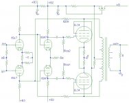
Thanks for that, KYW. I understood, from your initial description of your mods to the Shanling amp, the kind of FB loop you were using - as you said, similar to the Citation II arrangement.
I should try it, in place of the short NFB loop I currently have from the OP stage plate to the driver plate. I am inclined, though, to keep also the NFB from the 6SN7 plate to the 6SL7 plate, as I think this helps both DC and AC balance - what do you think?
I should try it, in place of the short NFB loop I currently have from the OP stage plate to the driver plate. I am inclined, though, to keep also the NFB from the 6SN7 plate to the 6SL7 plate, as I think this helps both DC and AC balance - what do you think?
Konnichiwa,
I tried this additional loop and in the end feltusing local degeneration in the 6SL7 Cathode to be preferable. Matter of taste I guess.
In my circuit the input valves in effect operate as strongly degenerated (and linearised) voltage to current converters which operate into a balanced "virtual AC ground" at the 6SN7 stage where the feedback loops are completed. This is very linear and has a good DC stability.
Sayonara
ray_moth said:I should try it, in place of the short NFB loop I currently have from the OP stage plate to the driver plate. I am inclined, though, to keep also the NFB from the 6SN7 plate to the 6SL7 plate, as I think this helps both DC and AC balance - what do you think?
I tried this additional loop and in the end feltusing local degeneration in the 6SL7 Cathode to be preferable. Matter of taste I guess.
In my circuit the input valves in effect operate as strongly degenerated (and linearised) voltage to current converters which operate into a balanced "virtual AC ground" at the 6SN7 stage where the feedback loops are completed. This is very linear and has a good DC stability.
Sayonara
I tried this additional loop and in the end felt using local degeneration in the 6SL7 Cathode to be preferable.
I've got both types in my current circuit (1k in each cathode of the 6SL7, plus the plate-to-plate NFB from 6SN7). Maybe that's belt-and-braces?
My thinking was that:
(1) The unbypassed 1k in each 6SL7 cathode would help both to make the gain less device-age-dependant and to allow the currents in the two halves of the splitter to equalize.
(2) The plate-to-plate NFB from the 6SN7 would give both AC and DC feedback, the latter helping to compensate for any DC imbalance in the 6SN7.
However, if DC stability its not llikely to be a problem, then I'll try it without the plate-plate NFB from the 6SN7.
I like the idea of DC coupling between the 6SL7 and 6SN7 because it eliminates a coupling capacitor from the feedback loop as per your schematic example (and as you have already mentioned). The only problem is the voltages! I can't have the 6SL7 plates sitting at +250v like they are at present (that's why I've got a step network in there now). However, I think I can get around this by creating a -100v supply for the 6AU6 LTP tail, which should allow me to drop the 6SL7 plates to about +100v, with a bit of adjustment in a few places (just have to be careful not to exceed cathode-heater voltage limit of the 6SL7 and 6AU7, which is about +-100v).
My mains tranny has a 50v 100mA winding, which I could use with a voltage doubler to get -100v. I only need about 10 mA, including the screen currents of the 6AU6 in each channel, so it should be well within the capabilities of the 50v winding. (This would allow me to use the 0v ground rail directly as the screen supply for the 6AU6, which should be very stable!)
- Status
- This old topic is closed. If you want to reopen this topic, contact a moderator using the "Report Post" button.
- Home
- Amplifiers
- Tubes / Valves
- Can partial feedback be as effective as global fb for decent damping factor?