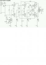
Finally converted amp to DC coupling and 2-stage NFB
Well, it took me long enough but now I've implemented the NFB suggestions kindly made by Kuei Yang Wang. It sounds really good - please see attached schema.
Well, it took me long enough but now I've implemented the NFB suggestions kindly made by Kuei Yang Wang. It sounds really good - please see attached schema.
Attachments
A little knowledge is a dangerous thing - or is it?
G'day from Oz,
I'm an ex Radio Trade Apprentice, Technical Assistant, Technical Officer and for the last 15 years a NON degree qualified senior electronic design engineer. That gives me a bad? habit of trying to reduce all the problems to first principals rather than rely on "what everyone knows". This occassionaly leads me into folly and I'll be the first to admit that my maths analysis skills sometimes are'nt up to the usual standard.
THESE ARE (IMO) THE BASIC FACTS To DEAL WITH.
1st - There are two frequency extremes to be concerned with in the output transformer:
At the low end increasing distortion results as the output tubes output impedance (rp) approaches the impedance of the Primary Inductance. This infers we want low tube rp.
At the high frequency end we have a "double" pole 12dB/octave roll off associated with leakage inductance and capacitance. Decreasing the rp of the output tubes shifts these poles higher in frequency.
Shunt feedback from the output valve anodes (by the partial feedback method or other) reduces output tube rp and hence reduces BOTH of these output transformer problems. It also therefore make applying a global feedback loop much easier when it comes to looking at stability.
The decreased rp also reflects to the secondary of the transformer as reduced output impedance ie improved damping factor.
The problem usually associated with partial feedback is that the grid capacitance of the output tube is effectively in parallel with the feedback resistor (ie driver stage load resistor which is connected to the output tube anode) and hence there are restrictions on the resistor value if you want to maintain a decent high frequency response. This is much more serious when using Triode Mode Outputs than when using Pentode Mode. (Ultralinear Mode will be somewhere in between) due to Miller capacitance.
In addition the partial feedback connection puts the output tube in a "Current to Voltage" converter topology (with the current to voltage conversion ratio set mostly by the feedback resistor value). This massively changes the demands on / required characteristics of the driver stage. Rather than the driver having to swing voltage it has to source current. Therefore you want a high rp driver stage (ideal current source behaviour) which will usually be done by a low gain triode stage with a large unbypassed cathode resistor or a much better idea is to use a pentode.
Much of this is covered above and some of it is glossed over or obscured in techno babble.
I hope this post will at least start you thinking in the right direction.
You will note that in the final circuit above shunt feedback is used BUT it isn't the "Partial Feedback" scheme.
Cheers,
Ian
Ping! KYW and others?
What Gingertube says seems to makes sense, in the light of John Broskie's aritcle on partial feedback, Patrick Turner's shunt feedback design from several years ago and Gary Pimm's PP-47 design. However, what Kuei Yang Wang says also makes sense to me, in particular the difficulty of driving OP tubes with significant anount of shunt feedback. Comments, anyone?
What Gingertube says seems to makes sense, in the light of John Broskie's aritcle on partial feedback, Patrick Turner's shunt feedback design from several years ago and Gary Pimm's PP-47 design. However, what Kuei Yang Wang says also makes sense to me, in particular the difficulty of driving OP tubes with significant anount of shunt feedback. Comments, anyone?
Re: Ping! KYW and others?
Konnichiwa,
It makes complete sense. However it is also a matter of definition. If we insist that "partial feedback" can only be output valve Anode to grid, then all this remains relevant, but also we are (again) very limited in how much NFB we can apply. And of course the circuit I suggested is then NOT partial feedback.
Now if we accept that "partial feedback" can mean "excludes output transformer and one or more stages of the overall amp" then what I suggested and what Ray_moth implemented is indeed partial feedback.
This is all semantics to me.
Well, what I suggested (and implement in my Shanling Amplifier Modifications) is in fact something that attemps to address as well as possible the following problems:
1) The longer the feedback loop (eg the more sstages and non-linear elements enclosed in the feedback loop) the more complex the overtone and intermodulation spectrum becomes. (as a shorthand rule, count the number of devices inside the feedback loop and take the square of that number, then square again and you have the order out to which the harmonic spectrum will extend, if the devices used have a 2/3 Squarelaw behaviour (Triode). Ideally we apply feedback ONLY around a single device. If we do so we have very limited amounts of feedback available, problems with the input capacitance and with the required degree of drive voltage/current. Thus we usually need to have two stages enclosed in the loop.
2) With 2 Stages in the loop, if we return the NFB to the Cathodes of the first of the 2 stages we introduce an addiiional common mode element into the circuit and increase the driver valves output impedance. Returning the feedback to an opposite phase grid avoids all of these problems.
3) With Push-Pull Amplifiers we find that distortion is cancelled if the two signals on the two halves of the transformer primary (assuming ideal balance of transformer) are identical but in opposite phase and if the distortion from each halve is present also in equal but identical phase in the other halve. In other words, if we can send the distortion from the Amplifiers section "1" into the section "2" while keeping the amplitude equal and the phase identical we eliminate it effectively. Perfect AC Balance in the phasesplitter an often hunted after attribute) actually does not establish such conditions, only crosscoupled balanced feedback as shown does.
4) If the output transformer is inside the feedback loop it limits the amount of NFB applicable severely and distorts much more (especially at low levels) than neccesary. Drive it from a low impedance and the problems are much reduced.
5) Due to the (inside the loop) load modulation when the Amplifier transtitions from Class A into Class B (one device cuts off) we desire an output stage as load tolerant as possible, using feedback as illustrated achieves that.
So, in the end the circuit I propose is related to "partial feedback" in the classical sense, but actually goes a step further and avoids most (if not all) of the pitfalls in conventional application of NFB and Push-Pull (Class AB). Maybe this clears up some confusion?
Sayonara
Konnichiwa,
ray_moth said:What Gingertube says seems to makes sense, in the light of John Broskie's aritcle on partial feedback, Patrick Turner's shunt feedback design from several years ago and Gary Pimm's PP-47 design.
It makes complete sense. However it is also a matter of definition. If we insist that "partial feedback" can only be output valve Anode to grid, then all this remains relevant, but also we are (again) very limited in how much NFB we can apply. And of course the circuit I suggested is then NOT partial feedback.
Now if we accept that "partial feedback" can mean "excludes output transformer and one or more stages of the overall amp" then what I suggested and what Ray_moth implemented is indeed partial feedback.
This is all semantics to me.
ray_moth said:However, what Kuei Yang Wang says also makes sense to me, in particular the difficulty of driving OP tubes with significant anount of shunt feedback. Comments, anyone?
Well, what I suggested (and implement in my Shanling Amplifier Modifications) is in fact something that attemps to address as well as possible the following problems:
1) The longer the feedback loop (eg the more sstages and non-linear elements enclosed in the feedback loop) the more complex the overtone and intermodulation spectrum becomes. (as a shorthand rule, count the number of devices inside the feedback loop and take the square of that number, then square again and you have the order out to which the harmonic spectrum will extend, if the devices used have a 2/3 Squarelaw behaviour (Triode). Ideally we apply feedback ONLY around a single device. If we do so we have very limited amounts of feedback available, problems with the input capacitance and with the required degree of drive voltage/current. Thus we usually need to have two stages enclosed in the loop.
2) With 2 Stages in the loop, if we return the NFB to the Cathodes of the first of the 2 stages we introduce an addiiional common mode element into the circuit and increase the driver valves output impedance. Returning the feedback to an opposite phase grid avoids all of these problems.
3) With Push-Pull Amplifiers we find that distortion is cancelled if the two signals on the two halves of the transformer primary (assuming ideal balance of transformer) are identical but in opposite phase and if the distortion from each halve is present also in equal but identical phase in the other halve. In other words, if we can send the distortion from the Amplifiers section "1" into the section "2" while keeping the amplitude equal and the phase identical we eliminate it effectively. Perfect AC Balance in the phasesplitter an often hunted after attribute) actually does not establish such conditions, only crosscoupled balanced feedback as shown does.
4) If the output transformer is inside the feedback loop it limits the amount of NFB applicable severely and distorts much more (especially at low levels) than neccesary. Drive it from a low impedance and the problems are much reduced.
5) Due to the (inside the loop) load modulation when the Amplifier transtitions from Class A into Class B (one device cuts off) we desire an output stage as load tolerant as possible, using feedback as illustrated achieves that.
So, in the end the circuit I propose is related to "partial feedback" in the classical sense, but actually goes a step further and avoids most (if not all) of the pitfalls in conventional application of NFB and Push-Pull (Class AB). Maybe this clears up some confusion?
Sayonara
- Status
- This old topic is closed. If you want to reopen this topic, contact a moderator using the "Report Post" button.