Just some offhand comments (I haven't had time to really look at this in depth):
Stabilizing this might be a bit of a challenge. One disadvantage to using a pair of cascaded triodes for the input stage is the number of poles this introduces. ("Stan, this is Wanda. Wanda, this is Stan.")
I couldn't make out the plate-to-plate Z. If it's 6K or so, you might consider going up on the B+ and down on the idle current.
Thanks for the larger version!
One more offhand comment: split-load inverters really don't need an adjustment, and without matched o'scope probes and a good sense of what you're doing, it's likely to end up misadjusted anyway. Just use matched plate and cathode resistors and it will work fine. Fewer parts, better reliability.
One more offhand comment: split-load inverters really don't need an adjustment, and without matched o'scope probes and a good sense of what you're doing, it's likely to end up misadjusted anyway. Just use matched plate and cathode resistors and it will work fine. Fewer parts, better reliability.
Any comments for this schem?
Soundwise, it's not likely to beat a basic Gainclone.
RC coupling vs DC coupling
@GAK
I would get rid of the RC coupling between the ECC81 and the ECC82 and use direct coupling into an ECC82 long-tailed pair. The circuit in your schem would be very diffcult to stablilize. Jax has a nice driver-amp/LTP posted somewhere on this forum. Or you could use the same circiut, but leave the 1st stage out of the feedback loop, using a 5687 as the 1st stage.
A 12AZ7 or a 12AV7/5965A would be much better than a 12AT7/ECC81 IMHO.
Another way you could go would be to use a Dynaco type driver stage such as a 6U8/ECF82 triode pentode, the pentode section direct coupled into a triode concerta phase splitter.
If you like I could post a couple of schems or I could email you a dozen or so for you to look over (as long as you post to let us all know how everything turns out!). The June/04 issue of Audio Express has a very good and fairly simple article on a 35W Triode/60W Ultralinear Control Amp which looks very similar as to what you're trying to do, except it leaves the 1st stage out of the feedback loop. It uses 6550's but can adopted to use EL34's
Cheers,
Wayne")
@GAK
I would get rid of the RC coupling between the ECC81 and the ECC82 and use direct coupling into an ECC82 long-tailed pair. The circuit in your schem would be very diffcult to stablilize. Jax has a nice driver-amp/LTP posted somewhere on this forum. Or you could use the same circiut, but leave the 1st stage out of the feedback loop, using a 5687 as the 1st stage.
A 12AZ7 or a 12AV7/5965A would be much better than a 12AT7/ECC81 IMHO.
Another way you could go would be to use a Dynaco type driver stage such as a 6U8/ECF82 triode pentode, the pentode section direct coupled into a triode concerta phase splitter.
If you like I could post a couple of schems or I could email you a dozen or so for you to look over (as long as you post to let us all know how everything turns out!). The June/04 issue of Audio Express has a very good and fairly simple article on a 35W Triode/60W Ultralinear Control Amp which looks very similar as to what you're trying to do, except it leaves the 1st stage out of the feedback loop. It uses 6550's but can adopted to use EL34's
Cheers,
Wayne
equal plate/cathode loads
@SY
Well yes you are correct but it depends on how the OPT primary is wound. Sometimes the lower output tube needs more drive as in the amp-kit I have, a mod'ed VAL VAA-70MkII. The concerta phase/splitter has a 36k anode load, while the cathode load resistor is 43k. I'm planning on changing that to a 6SL7 feeding a 6SN7 LTP soon.
Cheers,
Wayne
@SY
One more offhand comment: split-load inverters really don't need an adjustment, and without matched o'scope probes and a good sense of what you're doing, it's likely to end up misadjusted anyway. Just use matched plate and cathode resistors and it will work fine. Fewer parts, better reliability.
Well yes you are correct but it depends on how the OPT primary is wound. Sometimes the lower output tube needs more drive as in the amp-kit I have, a mod'ed VAL VAA-70MkII. The concerta phase/splitter has a 36k anode load, while the cathode load resistor is 43k. I'm planning on changing that to a 6SL7 feeding a 6SN7 LTP soon.
Cheers,
Wayne
If you've got an output transformer that's unbalanced in the bass and midrange, you've got problems. I suppose you could band-aid it a bit by deliberately unbalancing the phase splitter, but why select such a transformer in the first place?
I much prefer your suggested topology. In fact, I'm building one much like it right now, a 6SL7 cascode direct-coupled to a 6SN7 LTP.
I much prefer your suggested topology. In fact, I'm building one much like it right now, a 6SL7 cascode direct-coupled to a 6SN7 LTP.
@SY
It really has to do with the DC resistance of the two sides of the OPT primary. I didn't choose the OPT's, that's what the kit came with. Quite a few OPT's where made that way, it has to do with the way the primary was wound. Someone else posted about about this very same thing a while ago, but I can't find it. I'm also planning on chaging the OPT's also, some Hammond 1650N's at this point.
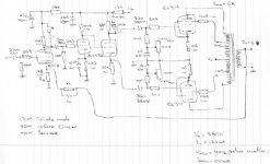
Using the trannies it came with, I get good bass, it's flat to below 20Hz, using a resistive load of course. I had to back off the feedback a little bit from the original circuit to get it stable at low frequences using my Polks as the load! Got supersonic bursts of oscillation riding on the waveform. Around 360kHz IIRC. There was also quite of bit of ringing with 10kHz square waves. Decreasing the feedback did the trick.
Here's a schem of how it stands at this point.
Wayne
It really has to do with the DC resistance of the two sides of the OPT primary. I didn't choose the OPT's, that's what the kit came with. Quite a few OPT's where made that way, it has to do with the way the primary was wound. Someone else posted about about this very same thing a while ago, but I can't find it. I'm also planning on chaging the OPT's also, some Hammond 1650N's at this point.
Using the trannies it came with, I get good bass, it's flat to below 20Hz, using a resistive load of course. I had to back off the feedback a little bit from the original circuit to get it stable at low frequences using my Polks as the load! Got supersonic bursts of oscillation riding on the waveform. Around 360kHz IIRC. There was also quite of bit of ringing with 10kHz square waves. Decreasing the feedback did the trick.
Here's a schem of how it stands at this point.
Wayne
Attachments
Ah, a variation of the Dyna circuit. Primary resistances on trannies like that rarely vary more than 20 or so ohms from side to side; the Eico HF87 transformers in front of me now run 130 and 150 ohms on each half. That's pretty insignificant imbalance compared to the 6600 ohm p-p impedance. At idle, you're drawing more-or-less 50 ma per tube, meaning that the plate voltage mismatch is roughly 1 volt. That's out of 380-400V. So I don't understand the rationale for unbalancing the split load, especially to the degree that you have done. The more significant error terms will be things like transconductance mismatch between the output tubes, which can be partly compensated for by unbalancing the idle currents just a bit to minimize 2nd HD.
One thing you might try for HF stabilizing is putting a high voltage cap across the lower resistance half of the opt (i.e., from the end to the CT). Something on the order of 270-470 pF would be appropriate.
One thing you might try for HF stabilizing is putting a high voltage cap across the lower resistance half of the opt (i.e., from the end to the CT). Something on the order of 270-470 pF would be appropriate.
@SY
The 36k and the 43k were in the original circiut, I haven't changed it! As I said this was a kit. I tried using equal loads and severe distortion was the result! Very early assymetrical clipping! This kit cost around $400 USD and used cheap Chinese parts. Please understand, I'm not bashing the Chinese people! (Just in case ya know!).
Now the PWR Xfrmer is excellant! 500mA secondary HV winding. Just gets a little warm after hours of operation. Highly over-rated for this amp. It really cooled down after I added a .01uF 2 kV ceramic cap across the HV winding. And a-lot of the buzzing went away. So I highly reccomend doing this if your HV supply uses sand rectumfiers (1N5408's).
At idle I'm drawing 35mA per tube and the tubes are very closely matched JJ E34L's. I haven't measured the DC resistance of the OPT's. Maybe I should get around to doing that to see how much of an inbalance there is. The OPT primay imp. is 5500 ohms. When I first saw the unequal load resistors my first thought was huhhh? I understand what you are saying and I really appreciate your input. All I can think of is that these tranny's must have a very large inbalance! So that's why I'm replacing those suckers.
Thanks
Wayne
The 36k and the 43k were in the original circiut, I haven't changed it! As I said this was a kit. I tried using equal loads and severe distortion was the result!
That's fascinating. What's the plate voltage on the pentode section of the 6U8?
What's the plate voltage on the pentode section of the 6U8?
120V on the right chan., 112V on the left. Tried adjusting the supply voltage up and down on both the pentode and triode sections in many combinations, AC inbalance worse in both directions, so I gave up!
I ended up changing the RC networks to the output stage (100k + 100nF to 270k + 220nF), the cap from the screen grid of the 6U8 (6F2) from 100nF to 1uF, dropped the 100nF input cap, decreased the grid leak from 470k to 120k (6F2 pentode section), got rid of the volume control, changed the cap in the RC anti-ringing network from 100pF to 82pF and the feedback resistor. It sounded horrible before I made those few changes! It sounded like you had your ear in a coffee can!
Was getting 25W right chan., 29W left. Now 38W right, 42W left (rated @40W per channel). Of course that's with the JJ's! The 1uF screen bypass cap made the biggest change in the bass response, clarity and power. I did notice the ringing was worse on the weaker (right) side. That was also the side that had the low freq. instability. So IMO the OPT's need changing! Whaddya expect for under 400 USD! I got a good power tranny and chassis, Hmmmm?? eh hum... (clearing throat). Hey it sounds better than my 225W sand amp! Oh yeah after 9 yrs it blew a 35 cent sand (transistor) driver on some Led Zepp! Got the replacement, just haven't got around to replacing it!
Wayne

Hmm…
@ cogsncogs
Can you post any interesting schem?
I saw again the article in audioXpress , the 35W triode / 60W UL.
What if I don’t use the first stage at all? I don’t need 60 watts and from 4 stages I’ll go to 3!
But if I do this how much watts I’ll have? And what changes I must do?
I also like the idea to leave the RC coupling between ECC81 and ECC82 and use direct coupling into an ECC82 LPT . Or why not to use 5687 and then looks like the above schem without the input stage.
Are these 5687 easy to find tubes?
My best choice is to use ECC81-82-83 and EL34.I already have these tubes.
Hi GAK
It's better to use 3 stages than 4.If you don't like 60 watts UL
leave the first stage of the 35W triode/60W UL.
I'm also searching for a nice schem about 30 W with EL34.
But I haven't tried 6550!!
Any comments btw these tubes?Of course 6550 are double the price.But if they worth the money...why not?
@coqsncoqs
Can you post any schem from your dozens?Or please e-mail me some of these.
Thanks
@GAK
Right now I'm leaving to Columbus (pick up my brother), will be back tonight, plus I'm configing a new box (comp.), Im on it now. So I'll post back with some schems ASAP... In the process of transfering files and apps to this new box!
The 5687's are in good supply and cheap!
www.tubesandmore.com
lo-medium mu, high perveance. A little shy on voltage gain, which is not a bad thing! Since you have the ECC81's and 82's, I would go with the ECC81 (1/2 for each channel) direct coupled into an ECC82 LTP, and some Hammond iron. A 6CG7/6FQ7 would be even better for the LTP.
Here's a schem of a driver stage I was working on w/ arnoldc
Cheers
Wayne
Attachments

linerity, linerity
@resident
The 6SN7 and 6FQ7 are much more linear than any ECC81, 82, 83. A 6CG7/6FQ7 is basicaly a 6SN7 (same electrical characteristics, but they sound different) in a 9 pin noval (B9A). The reason the 6SN7 was used as the 1st stage I believe, was the way arnoldc had his chassis laid out. If it was up to me (from scratch) it would be ALL 6SN7's or 6FQ7 --> 6SN7GTB, 450V max anode compaired to 330V for the 6FQ7, get bigger swing hehe. But hey, it may sound better the other way around! I'm still going with a 6SL7 --> 6SN7 for my new driver stage, all Octal!
If you want (need) more gain use a 5965A or a 12AV7 as 1st stage, again more linear than an ECC81 and they're dirt cheap! I got me a butt-load of them last month! NOS Sylvania's and RCA's, looked like they were made by the same manufactuer, different paint job! When I get things moved over to new box, I may post a couple dia's.
BTW, I believe arnoldc used a 6SN7 into an ECC82/12AU7A LTP.
Wayne
@resident
The 6SN7 and 6FQ7 are much more linear than any ECC81, 82, 83. A 6CG7/6FQ7 is basicaly a 6SN7 (same electrical characteristics, but they sound different
) in a 9 pin noval (B9A). The reason the 6SN7 was used as the 1st stage I believe, was the way arnoldc had his chassis laid out. If it was up to me (from scratch) it would be ALL 6SN7's or 6FQ7 --> 6SN7GTB, 450V max anode compaired to 330V for the 6FQ7, get bigger swing hehe. But hey, it may sound better the other way around! I'm still going with a 6SL7 --> 6SN7 for my new driver stage, all Octal!If you want (need) more gain use a 5965A or a 12AV7 as 1st stage, again more linear than an ECC81 and they're dirt cheap! I got me a butt-load of them last month! NOS Sylvania's and RCA's, looked like they were made by the same manufactuer, different paint job! When I get things moved over to new box, I may post a couple dia's.
BTW, I believe arnoldc used a 6SN7 into an ECC82/12AU7A LTP.
Wayne
Re: linerity, linerity
yes wayne, i did. the PP amp is still in the prototype chassis, sounding better than before thanks to youcogsncogs said:BTW, I believe arnoldc used a 6SN7 into an ECC82/12AU7A LTP.
Wayne
cogsncogs, I have bought a VAA70 MkII Kit myself (I am a tube beginner). Found your schematic extremely useful to clarify some values (the 36k and 43k resistors R5 & R6 in your drawing are shown as 100k / 36k in the construction manual. The PCB print seems to be more correct. But there is no place for the second 100uF/400V Capacitor on either the supply or the amp PCB. Do I have to drill the holes into the PCB? Maybe you have a schematic of your power supply too?
theduke
theduke
- Status
- This old topic is closed. If you want to reopen this topic, contact a moderator using the "Report Post" button.
- Home
- Amplifiers
- Tubes / Valves
- EL 34 30W ultra linear