thankyou! Yes there's place for C4 in the middle of the amp board but none for C3 which I think has to go on the supply PCB. What is D6 for? Are C11, C12, C13 added by you?
The manual supposes rectification of the bias with one 1N5408. I think full rect gives less ripple? Have you opted for AC heating of filaments?
Cheers
theduke
The manual supposes rectification of the bias with one 1N5408. I think full rect gives less ripple? Have you opted for AC heating of filaments?
Cheers
theduke
@ theduke
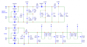
Yes C3 is mounted on the PSU board, on the foil side. D6 is what's known as a "poor man's regulator"! It prevents C3 and C4 from discharging back into C1 and C2 during peak current draw of the output stage. R23 is a bleeder for C3 and C4. There are provisions on the driver board for C12, C13 and R23. C11 was added by me to reduce rectifier switching noise. Also it would be a good idea to bypass the HT, Bias, and the 6.3V driver filament secondaries with a 0.01uF 2kV ceramic capacitor. Do not bypass the output tube secondaries. These are left floating, this can be done because the outputs use fixed bias and the EL34 cathodes are at a low potential. If cathode (self) bias were to be used they should have a ground reference using two 100R-330R resistors in series across the secondaries with the junction of the two resistors grounded. Or a 100R-500R WW pot with the wiper at ground.
I'm using DC for the driver tube(s) filament supply using a 1N5408 bridge followed by two caps in = (3300uF+2200uf) > 0.22R 3W WW > (4700uF+3300uF). All caps 16WV. I used those because that's what I had lying around!
I used a full wave bridge for the bias supply, 4) 1N4007's. There's a provision for that also on the PSU pcb, as you may know already. Yes... much less ripple and quite a bit more voltage. I changed the 1st filter cap (C9) in the bias supply to 160WV because of there being around 100V at that position, for a safety margin.
For C11, C12, and C13 I'm using 630V Solen polypropylene film caps. They fit rather nicely. Also if I may suggest, change the coupling caps to the EL34's to 220nF (630V Solen's again 'cause they fit nicely) and the grid leaks to 270k 1W carbon films or metal oxide matched to within 1% Also the 220nF caps should be matched as close as possible. And don't forget to change the screen bypass caps on the 6F2's (6U8, 6EA8, 6GH8) to 1uF 250V polypropylene! That's the one cap that changed the sonic character of the amp for the MUCH better! Use the best cap you can afford here and that will fit without too much fuss (I had to drill a couple of holes!). And one more thing in case you missed it on my schem, change the 100pF 150V ceramic disc to 82pF-68pF NPO or COG 500V ceramic.
For the 10R 5W WW cathode resistors that the EL34's are standing on, change to 10R 2W or even 1W metal oxide. And be sure to set your bias to 35mA or up to 40mA @ the most.
You may also want add a .01uF 2kV ceramic (or resistor 130R resistor plus a .01uF cap in series) across the mains switch to prevent arching/welding of the switch contacts.
As for the output tubes I highly recommend the JJ E34L's. They seem to work really well in this amp. And one more thing, remove the 1k metal oxide grid stopper resistors to the outputs and replace with 1k carbon composition resistors and connect them directly to the output valve socket tabs and as close the coupling caps as possible on the PCB...
Hope this answers all of your questions and the ones you DIDN'T ask about, and improves your amp! Have fun!
BTW I don't recommend increasing the value of C1 and C2! It can lead to instability problems! At least it did with my amp...
 Layout seems to be very critical in this amp, HF instability. I blame it on the OPT's. If you incounter some HF instability increase the feedback resistors as shown in the amp schematic.
The Solen's sound rather harsh at first, but after they break in they're not too bad!?... I find the Dayton film and foil polyproylene's (Parts Express) to be much better but they are rather large and therefore you have some drilling, fudging to do.
Wayne
Yes C3 is mounted on the PSU board, on the foil side. D6 is what's known as a "poor man's regulator"! It prevents C3 and C4 from discharging back into C1 and C2 during peak current draw of the output stage. R23 is a bleeder for C3 and C4. There are provisions on the driver board for C12, C13 and R23. C11 was added by me to reduce rectifier switching noise. Also it would be a good idea to bypass the HT, Bias, and the 6.3V driver filament secondaries with a 0.01uF 2kV ceramic capacitor. Do not bypass the output tube secondaries. These are left floating, this can be done because the outputs use fixed bias and the EL34 cathodes are at a low potential. If cathode (self) bias were to be used they should have a ground reference using two 100R-330R resistors in series across the secondaries with the junction of the two resistors grounded. Or a 100R-500R WW pot with the wiper at ground.
I'm using DC for the driver tube(s) filament supply using a 1N5408 bridge followed by two caps in = (3300uF+2200uf) > 0.22R 3W WW > (4700uF+3300uF). All caps 16WV. I used those because that's what I had lying around!
I used a full wave bridge for the bias supply, 4) 1N4007's. There's a provision for that also on the PSU pcb, as you may know already. Yes... much less ripple and quite a bit more voltage. I changed the 1st filter cap (C9) in the bias supply to 160WV because of there being around 100V at that position, for a safety margin.
For C11, C12, and C13 I'm using 630V Solen polypropylene film caps. They fit rather nicely. Also if I may suggest, change the coupling caps to the EL34's to 220nF (630V Solen's again 'cause they fit nicely) and the grid leaks to 270k 1W carbon films or metal oxide matched to within 1% Also the 220nF caps should be matched as close as possible. And don't forget to change the screen bypass caps on the 6F2's (6U8, 6EA8, 6GH8) to 1uF 250V polypropylene! That's the one cap that changed the sonic character of the amp for the MUCH better! Use the best cap you can afford here and that will fit without too much fuss (I had to drill a couple of holes!). And one more thing in case you missed it on my schem, change the 100pF 150V ceramic disc to 82pF-68pF NPO or COG 500V ceramic.
For the 10R 5W WW cathode resistors that the EL34's are standing on, change to 10R 2W or even 1W metal oxide. And be sure to set your bias to 35mA or up to 40mA @ the most.
You may also want add a .01uF 2kV ceramic (or resistor 130R resistor plus a .01uF cap in series) across the mains switch to prevent arching/welding of the switch contacts.
As for the output tubes I highly recommend the JJ E34L's. They seem to work really well in this amp. And one more thing, remove the 1k metal oxide grid stopper resistors to the outputs and replace with 1k carbon composition resistors and connect them directly to the output valve socket tabs and as close the coupling caps as possible on the PCB...
Hope this answers all of your questions and the ones you DIDN'T ask about, and improves your amp! Have fun!
BTW I don't recommend increasing the value of C1 and C2! It can lead to instability problems! At least it did with my amp...
Layout seems to be very critical in this amp, HF instability. I blame it on the OPT's. If you incounter some HF instability increase the feedback resistors as shown in the amp schematic.The Solen's sound rather harsh at first, but after they break in they're not too bad!?... I find the Dayton film and foil polyproylene's (Parts Express) to be much better but they are rather large and therefore you have some drilling, fudging to do.
Wayne
wow, this is a wealth of info! I will read it over and over and try it all out step by step or in the first place. I hope I will find the spare time to finish this amp soon.
You answered nearly all of my questions. Just a couple of things: Is the R between the filter caps of the driver filament supply necessary or could I leave it out? So I should adjust the bias for current, not for voltage? And finally does the driver cathode to ground R have to be 200R or could I use 220R?
thankyou
theduke
QUOTE]And finally does the driver cathode to ground R have to be 200R or could I use 220R?[/QUOTE]
In the earlier versions 220R was used but in the newer revised version it was changed to 200R You can use use a 220R at the expense of a very slightly lowering of gain along with a slight increase of NFB from the OPT. And a slightly higher plate voltage of the pentode section of the 6F2. It really shouldn't make that much of a difference in performance! IMHO I would keep the 0.22R 3W resistor to lower the surge current at turn on with a slightly lowering of filament voltage to the driver tubes and a subsequent lowering of ripple current. Keeping that resistor will also allow you to increase the value of the last two caps without any ill effects to further reduce ripple current at the same time slightly increasing the voltage seen at driver tube filaments, but I find that 6.0 - 6.1V to be about perfect!
Cheers
Wayne
So I should adjust the bias for current, not for voltage?
YES, current for each output! 350mV - 400mV across each 10R resistor, which translates to 35mA - 40mA for each EL34. Of course that's matched for each EL34 pair!
Wayne

Originally posted by the duke:
the 2 R's in = to the HV filter caps are bleeders, right (R21, R22)?
Well yes and also to equalize the voltage across the two caps. The difference of 5% is insignificant.
originally posted by aht:
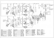
I got a schematic from Antique Sound Labs AQ-1003
Yeah post'em those things! It's cool that you have the schem, but why not share'em with us?
@ theduke
You really have a nice amp for the money. Follow my suggestions and you will be pleasantly surprised! A good scope of at least 20 - 30MHz to do your testing/tweaking is almost a must! Right now I'm listening to peter gabriel's album Security and I must say I'm very into the experience!
I have some modifications in mind that I like to perform on this amp that should improve the listening experience/performance of this darn thing! If you like I will post some other, more extensive modifications. Like a 6SL7 amp driving a 6SN7 long-tail-pair! SWEET! A little short on funds at the moment but that should CHANGE SOON! Take my advice and change out the outputs from the Chinese EL34's to EI's E34L's, 15% more output and much easier to drive! Higher gm.
Cheers
Wayne
BTW: Get/Build you a VALVE line-amp to drive that sucker! Even if some-one tells you that you don't need it!
My file is too large
Everybody can mail to me for highres schematic and PCB-ARTWORK
ahtweb@hotmail.com
regard
AHT
Everybody can mail to me for highres schematic and PCB-ARTWORK
ahtweb@hotmail.com
regard
AHT
Attachments
@cogsncogs
I got this thing off ebay and I have to say it looks like quality to me. Like you wrote the power transformer is enormous. My kitchen scale only goes to 5kg
Visually the OPTs appeal to me also. This amp seems to get spread across the globe under various brands. I got a complete kit, even solder was included... The manual is crap, but at least one gets a basic picture. Holding the first quad of mysterious chinese tubes in my hands was a good feeling for me
This is my first tube amp (ok amp in general), and I want to do it soon and get into it... I will implement most of your suggestions but I won't by no expensive stuff but I will lookout for a quad of E34L's! Seems there are no carbon composite resistors where I live. Ok and a scope is out of reach for the moment
I will build a 12 step switch attenuator with metal films for this buddy and maybe throw the input cap away... (hey I don't wanna aplify dc ok) Pre-wise it's gotta be a plain switch maybe
@aht
Looking at that scheme I thought it was mine. looks good... but i'm not into tube waters yet !
theduke
I got this thing off ebay and I have to say it looks like quality to me. Like you wrote the power transformer is enormous. My kitchen scale only goes to 5kg
Visually the OPTs appeal to me also. This amp seems to get spread across the globe under various brands. I got a complete kit, even solder was included... The manual is crap, but at least one gets a basic picture. Holding the first quad of mysterious chinese tubes in my hands was a good feeling for me
This is my first tube amp (ok amp in general), and I want to do it soon and get into it... I will implement most of your suggestions but I won't by no expensive stuff
but I will lookout for a quad of E34L's! Seems there are no carbon composite resistors where I live. Ok and a scope is out of reach for the moment I will build a 12 step switch attenuator with metal films for this buddy and maybe throw the input cap away... (hey I don't wanna aplify dc ok) Pre-wise it's gotta be a plain switch maybe
@aht
Looking at that scheme I thought it was mine
. looks good... but i'm not into tube waters yet !theduke
I will build a 12 step switch attenuator with metal films for this buddy and maybe throw the input cap away... (hey I don't wanna aplify dc ok)
Even if you use a stepped attenuator keep the grid leak resistor, the value at least 5x the maximum imp of the attenuator, to safeguard against any pops and to provide a short HF/RF path to ground for the grid of the 6U8 pentode section. Also do not use a grid stopper on the 6U8, I've tried that on my amp and it did reduce some of the ringing on both channels but the left channel became unstable (OPT's differences). Burst of HF oscillation riding on low frequency waveforms below 50- 60 Hz IIRC with my Polks as the load. With a resistive load, no such artifacts. I now use diy'ed Dayton 8" MTM's though.
But once I increased the value of the NFB resistor the amp became stable and a lot of the ringing went away (this is were a scope comes in handy!). You can hear it as a buzzing sound on bass notes! But because of the Q-control (variances) of the OPT's (maybe even diff manufacturers) and in combination of what spkrs you use your amp maybe stable as is. But that is usually an indication of bad OPT design and or messed up schem for the amp. The original schem shows the NFB resistor (5.6k) connected to the 8 ohm tap as for use w/an 8 ohm spkr. I find that's the value for a 4 ohm spkr on the 4 ohm tap and that 7.87k should be used for the 8 ohm tap! Too much NFB! And also watch out for mislabeling of the OPT's (wire color also!) following the schem/manual precisely, I had to reverse the OPT's primaries! Even bringing a probe near the cathodyne phase splitter (triode section) either stopped the oscillation or caused it! Very frustrating! But I've got it stable??, but only after a lot of tweaking! One good thing I can say about this amp is that the deep bass is good for a 40W toob-amp! Rattles the windows! Using a 40Hz square wave into a resistive load shows very little tilt. Of course that's with my modifications!
I hope some of this provides some info and a little insight into the quirks of this amp! As for amplifying DC, just make sure your sources have no DC offset on their outputs. They shouldn't anyway!! A cap that can be left out is best left out! But if you feel you need a cap there, then a high quality cap is a must! It can only degrade the sound.
Cheers
Wayne
BTW the instability was present in the stock amp before any modifications.
And also watch out for mislabeling of the OPT's (wire color also!) following the schem/manual precisely, I had to reverse the OPT's primaries!
Oh, could you be more precise about that?
cogsncogs, thank you so much for your input about this project! I think I will get a decent amp with the help you posted...
theduke
...and one more question: I want to connect the chassis to the "Schutzleiter" in one point. This is the third connection from the power outlet (protection ground, safety ground ??). Should I also connect this potential to the circuit ground? I feel like connecting the amplifier circuit ground to the pre-amplifier ground but not to that Schutzleiter ("house ground"). (sorry for that word So all the terminals would be isolated from chassis
regards
theduke
So all the terminals would be isolated from chassisregards
theduke
@ theduke
The amplifier chassis should be at EARTH gnd. Is your preamp chassis gnd'ed at the outlet (earth gnd) also? If so lift it using a cheater in case you get ground loop hum problem. The "safety ground" should be connected to the chassis via the screw that's labeled gnd, not the signal or PSU gnd. I have digital camera so, I'm palnning on checking the bias of my amp and a little tweaking (us diy'ers are always fixing things that aren't BROKE!) and I'll take a little pic of what I'm describing and post it. That safety gnd is very important in case a short developes say in your PWR xfrmr to the amp chassis! If that were to happen, you and yours could get a very nasty or LETHAL shock from touching the chassis or any component that's attached to the amp via the gnd of you interconnects!
As for the OPT's primary connections; if you get a howl from your spkrs, swap the OPT's anode and screen taps between the two EL34's. In other words take both anode and screen taps from one EL34 and connect to the other EL34 and vice versa. I hope that was clear enough.
As for the opt secondary, the green wire = 8R tap, blue= 4R tap, Black= GND. At least it should be! For your spkr gnd, run a wire from each spkr gnd post to the gnd foil near the 100uF cap on the driver pcb. Run a 20-18 ga wire from there to the PSU gnd but not the chassis gnd screw where the earth gnd from the mains connects. The only place the signal/PSU gnd connects to the chassis should be at the RCA (interconnects) jacks at the front of the amp. If you don't get a good/reliable gnd connection there, scrap away a little of the black paint.
I'll post a pic of the underside of the amp at the first chance I get. Gotta do some shopping this afternoon, maybe 2-nite. hope this answers some of your questions.
Wayne
The amplifier chassis should be at EARTH gnd. Is your preamp chassis gnd'ed at the outlet (earth gnd) also? If so lift it using a cheater in case you get ground loop hum problem. The "safety ground" should be connected to the chassis via the screw that's labeled gnd, not the signal or PSU gnd. I have digital camera so, I'm palnning on checking the bias of my amp and a little tweaking (us diy'ers are always fixing things that aren't BROKE!) and I'll take a little pic of what I'm describing and post it. That safety gnd is very important in case a short developes say in your PWR xfrmr to the amp chassis! If that were to happen, you and yours could get a very nasty or LETHAL
shock from touching the chassis or any component that's attached to the amp via the gnd of you interconnects!As for the OPT's primary connections; if you get a howl from your spkrs, swap the OPT's anode and screen taps between the two EL34's. In other words take both anode and screen taps from one EL34 and connect to the other EL34 and vice versa. I hope that was clear enough.
As for the opt secondary, the green wire = 8R tap, blue= 4R tap, Black= GND. At least it should be! For your spkr gnd, run a wire from each spkr gnd post to the gnd foil near the 100uF cap on the driver pcb. Run a 20-18 ga wire from there to the PSU gnd but not the chassis gnd screw where the earth gnd from the mains connects. The only place the signal/PSU gnd connects to the chassis should be at the RCA (interconnects) jacks at the front of the amp. If you don't get a good/reliable gnd connection there, scrap away a little of the black paint.
I'll post a pic of the underside of the amp at the first chance I get. Gotta do some shopping this afternoon, maybe 2-nite. hope this answers some of your questions.
Wayne
ECC82/83 - EL34 combo?
Switch'em around, make that an ECC83/82 - EL34 combo. There there, that's much better! This is only the driver circuit for an EL34 pair and has not been built and tested by me. This is only a simulation and it sim'ed good and will work. Of course there will always be some tweaking to do. That's what DIY'ing is all about! And yes you can use a 5U4 for the rectifier depending on your PWR transformer and the voltage you want to run the EL34's at.
You can sub an ECC83 for the 5751
Wayne
Attachments
- Status
- This old topic is closed. If you want to reopen this topic, contact a moderator using the "Report Post" button.
- Home
- Amplifiers
- Tubes / Valves
- EL 34 30W ultra linear