Hi,
I bought a "CAT SL1 improved" kit from http://www.diyclub.biz/catalog/product_info.php?cPath=106_145&products_id=273 . I guess that it isn't a copy of SL1, but some ideas may be taken from there.
The problem is that the gain of this board is way too high for me since my poweramp's sensitivy is 300mV - I can't more than the first few % of volume control.
What changes would you suggest, i have tried to play with R1/R2, R10 and R11/R12 but can't guess the right values.
Lowering R2 and increasing the R1 will drop the gain, but I guess the highs are gone after that. Lowering the R10 will make the sound dull.
What would be your recommendations?
Thank you for your answers,
Attachments
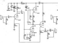
OMG! A mu-stage with a CF after it... WTF!
Sigh... probably trying to waste tubes. Wish I could have a talk with whoever drew that... while holding a bat that is.
Anyway, a 12AU7 in place of the AX should drop a few dB... R5 and R8 will want to be more like 1k, I think.
Tim
Sigh... probably trying to waste tubes. Wish I could have a talk with whoever drew that... while holding a bat that is.
Anyway, a 12AU7 in place of the AX should drop a few dB... R5 and R8 will want to be more like 1k, I think.
Tim
Same here!I bought a "CAT SL1 improved" kit from http://www.diyclub.biz/catalog/prod...products_id=273 . I guess that it isn't a copy of SL1, but some ideas may be taken from there.
")
I bought the same pc board several months ago!
Yes, the gain is too much. I can't solve the problem either. I simply unplugged the filament for V4!

Well, with the 6dj8 for output, the preamp sounds ok now. But....
why do I need V2 there!
C.C.
Hi,
That's actually the only one I would have left as is....
Cheers,
I simply unplugged the filament for V4!
That's actually the only one I would have left as is....
Cheers,
Sch3mat1c said:OMG! A mu-stage with a CF after it... WTF!
Sigh... probably trying to waste tubes. Wish I could have a talk with whoever drew that... while holding a bat that is.
I thought that odd too Tim.
First, the audio take-off is in the wrong spot - it should be off the top tube's cathode in the mu stage and.....
They can do the stereo circuit with 3, not 4 tubes and all three 12AU7 or 12AT7 if they REALLY need gain, for simplicity and cost effectiveness.
<insert 100 rolling eyes here>
Hi,
In which case you actually take the signal straight off the cathode of the 12AU7A.
You should now have a CF with probably some signal fed back from the 12AX7A mu-follower but I'm not sure it would result in real gain. I don't think so...
If you'd want to take advantage of the properties of the mu-follower then, yes.
Since they stick a CF at the output anyway it doesn't really matter anymore anyway.
What you have now is CF in, mu-stage with a 12AX7A no less, followed by another CF...DUH...
This whole thing kind of reminds me of the Jadis linestage which is equally errr...silly.
Cheers,
It sounds ok when I cut the filament for V4. No kidding.
In which case you actually take the signal straight off the cathode of the 12AU7A.
You should now have a CF with probably some signal fed back from the 12AX7A mu-follower but I'm not sure it would result in real gain. I don't think so...
First, the audio take-off is in the wrong spot - it should be off the top tube's cathode in the mu stage and.....
If you'd want to take advantage of the properties of the mu-follower then, yes.
Since they stick a CF at the output anyway it doesn't really matter anymore anyway.
What you have now is CF in, mu-stage with a 12AX7A no less, followed by another CF...DUH...
This whole thing kind of reminds me of the Jadis linestage which is equally errr...silly.
Cheers,
The gain is set by the feedback loop, so changing/supressing the 12ax7 won't modify it.
the problem is that the voltage accross R3 defines the bias for the 12au7.
because the current in the 12au7 is negligible , you have
Gain = R10/R3= 20 (26dB)
and 12au7 Bias = (output DC) *R3/(R3+R10) = 120V* 1/21 =5,7V
If you increase R3, you need to increase R10 (and vice versa) to maintain the bias voltage for the 12au7.
So if you want to reduce the gain, you can:
-put a divider in the output (this will also reduce the hum!): simple, cheap and very effective!
-change the input valve for another that will accept higher bias voltage (if any) and reduce R10
-bias the 12au7 input (this requires an input cap and a negative supply)
-reduce the output DC, ie the 6922 input voltage either through a divider from the mustage output (decouple the musatge from the 6922 cathode follower using a capacitor , and bias the 6922 grid at 50V with two resistors), you can then halve R10.
-use a combination of the three.
just put that pcb in deepest drawer in your room ,then make some PTP decent construction ;
you can find it at Diyaudio or somewhere else ,but you really don't need any gain with your amp's sensitivity .
try something ala Wright's SLCF or one of FDegrove's ideas
in any case-you need just CF or AF with unity gain
you can find it at Diyaudio or somewhere else ,but you really don't need any gain with your amp's sensitivity .
try something ala Wright's SLCF or one of FDegrove's ideas
in any case-you need just CF or AF with unity gain
This is a very old thread, but the preamp is such a poorly thought out circuit - especially for someone with amps with 300mV input sensitivity that I just had to add something.
As Greg said, the signal take off point for the m-follower is wrong. In this case, the output impedance of the stage is closer to ra than it is to ra/(m+1). To the designer's credit, a m-follower with 12AX7s running at next to no current can't drive a capacitive cable or capacitive amp input without running into trouble despite the low-ish output impedance (distortion would increase markedly with frequency) - so the cathode follower is a good thing.
Actually, I think the 6DJ8 cathode follower is the only good thing in this preamp - especially since no gain is required. If the original poster is still around, R1 should go to the 6DJ8's grid and get rid of everything in between.
Or sell the thing and put an attenuator at the input of the poweramp.SY said:With 300 mV of sensitivity, why do you even need ANY gain out of the line stage? You can lose the three tubes used in the gain stage and just run it as a cathode follower.
T-wong from WWW.kitparts carries the same ****. I believe its a copy of what you bought. Also from Hong Kong
Have any hum problems with it?
Have any hum problems with it?
No hum problem at all.Have any hum problems with it?
It still sounds loud after I decrease the R10. I have already pull out the main PC board. I am tryng to inplant a JP200 inside. The PCB is coming. I hope this one can resore my comfidence of buing PCboards.
Lhchen

Hi,
Only on the surface but since the mu-follower is DC coupled to the CF, taking the signal off the plate isn't such a bad idea after all.
Still the whole idea looks like an exercise in complexity rather than an exercise in simplicity....and hums too....
What's the B+ of that thing anyway?
Sometimes you can't help but wonder what the heck they're up you, can't you?........Yikes....
The whole just looks as if the just ripped out the RIAA components of their phonostage and be done with it....
Sigh,
As Greg said, the signal take off point for the m-follower is wrong.
Only on the surface but since the mu-follower is DC coupled to the CF, taking the signal off the plate isn't such a bad idea after all.
Still the whole idea looks like an exercise in complexity rather than an exercise in simplicity....and hums too....
What's the B+ of that thing anyway?
Cascaded 12AX7 with 12AX7 cathode follower output
Sometimes you can't help but wonder what the heck they're up you, can't you?........Yikes....
The whole just looks as if the just ripped out the RIAA components of their phonostage and be done with it....
Sigh,
fdegrove said:Only on the surface but since the mu-follower is DC coupled to the CF, taking the signal off the plate isn't such a bad idea after all.
Ah, I see. Perhaps I was mistaken... Low Zout isn't really that much of an issue anyway because of the cathode followers high Zin, and if it does away with the need for additional RC coupling all the better. But I still don't like the design.
fdegrove said:Still the whole idea looks like an exercise in complexity rather than an exercise in simplicity....and hums too....
Right on!
fdegrove said:What's the B+ of that thing anyway?
I don't know, but the JP-200 clone that contaxchen wants to build runs at 360V.
fdegrove said:Sometimes you can't help but wonder what the heck they're up you, can't you?........Yikes....
The whole just looks as if the just ripped out the RIAA components of their phonostage and be done with it....
Sigh,
Sigh indeed.

There was a schematic of the JP-200 round here somewhere but it seems to have disappeared. From memory - it was a similarly complicated preamp - way too much gain (which has to be thrown away in a global feedback loop), and a 12AX7 cathode follower output. You are quite right, it does strangely resemble a phono preamp...
Somebody is trying up to 450V!I don't know, but the JP-200 clone that contaxchen wants to build runs at 360V.
Does anyone have the original CAT schematic they can post?
I bought the Marantz line stage board from them and its actually pretty darn close to the Marantz 7 schematic.... VERY well made PCB but the sizing for some of the parts leaves me a bit mystified. but then the Chineese are pretty mysterious anyway......
Mark
I bought the Marantz line stage board from them and its actually pretty darn close to the Marantz 7 schematic.... VERY well made PCB but the sizing for some of the parts leaves me a bit mystified. but then the Chineese are pretty mysterious anyway......
Mark
Does anyone have the original CAT schematic they can post?
Impossible... I don't think it is availible.
As for the schematics for JP200.... There is a so-called schematics availibe over internet. You gotta use Chinese google. It seems that this cloned board is closer to the real JP200 which use 8pcs of 12at7 while the cloned one used only 6.
M7 's schematics is well-known. The real difficulty to clone this one is that you can't find those components on the market! You can only buy those component from a museum.
- Status
- This old topic is closed. If you want to reopen this topic, contact a moderator using the "Report Post" button.
- Home
- Amplifiers
- Tubes / Valves
- Too much gain